


|
Caution | Read the manual before operating this equipment. No user serviceable parts. Only qualified service personnel shall service this equipment. |

|
Electric Shock Hazard | Danger High Voltage - Disconnect all sources before servicing. |
We provide you with an accessory kit that includes everything you need to get started, including:
1.5 mL Conical Tubes
15 mL Conical Tubes
50 mL Conical Tubes
1.5 mL Tube Adapters
15 mL Tube Adapters
50 mL Tube Adapters
1.5 mL Tube Rack
15 mL Tube Rack
50 mL Tube Rack
Chip Rack
10 g Calibration Weight
100 g Calibration Weight
Ethernet Cable
Power Cable
Long Base Chip Gasket
Buffer Needle (MM P# 75165A67 and 51525K122)
Pneumatic Tubing
Permeate Container (MM P# 3795T25)
Installation Certificates (for customers located in China only)
Warranty Letters (for customers located in China only)
Before running an experiment, we recommend that you familiarize yourself with each of the aµtoPULSE components.
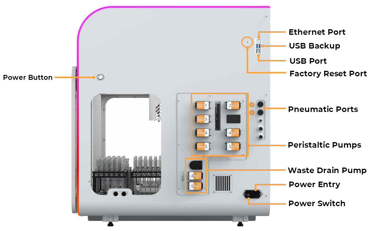
aµtoPULSE Right Side View
Power Button: Press the button to turn the instrument on or off.
Ethernet Port: Provides a peer-to-peer connection through the hard wire.
USB Backup: Serves as backup storage if the Micro SD Card in the instrument fails.
USB Port: Connects external devices like USB drives to save logs or manually update aµtoPULSE software when an Internet connection is unavailable.
Factory Reset Button: Resets the system to factory settings to resolve operational issues.
Pneumatic Ports: Facilitates the liquid transfer necessary for profile runs.
Peristaltic Pumps (Buffer and Cleaning): Transfers buffer and cleaning solutions throughout the system.
Waste Drain Pump: Removes waste liquid from the system for efficient operation.
Power Entry: Plug in the power cable here to supply power to the system.
Power Switch: Connects the aµtoPULSE to a 220V power source.
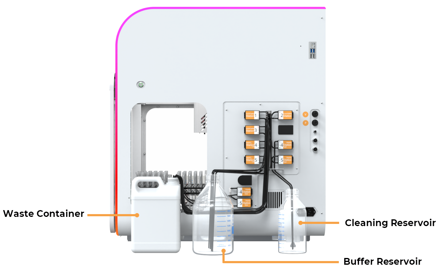
Reservoir and Waste Container
Buffer or Cleaning Reservoir: Stores buffer or cleaning solution needed during profile runs.
Waste Container: Collects waste permeate from the instrument.
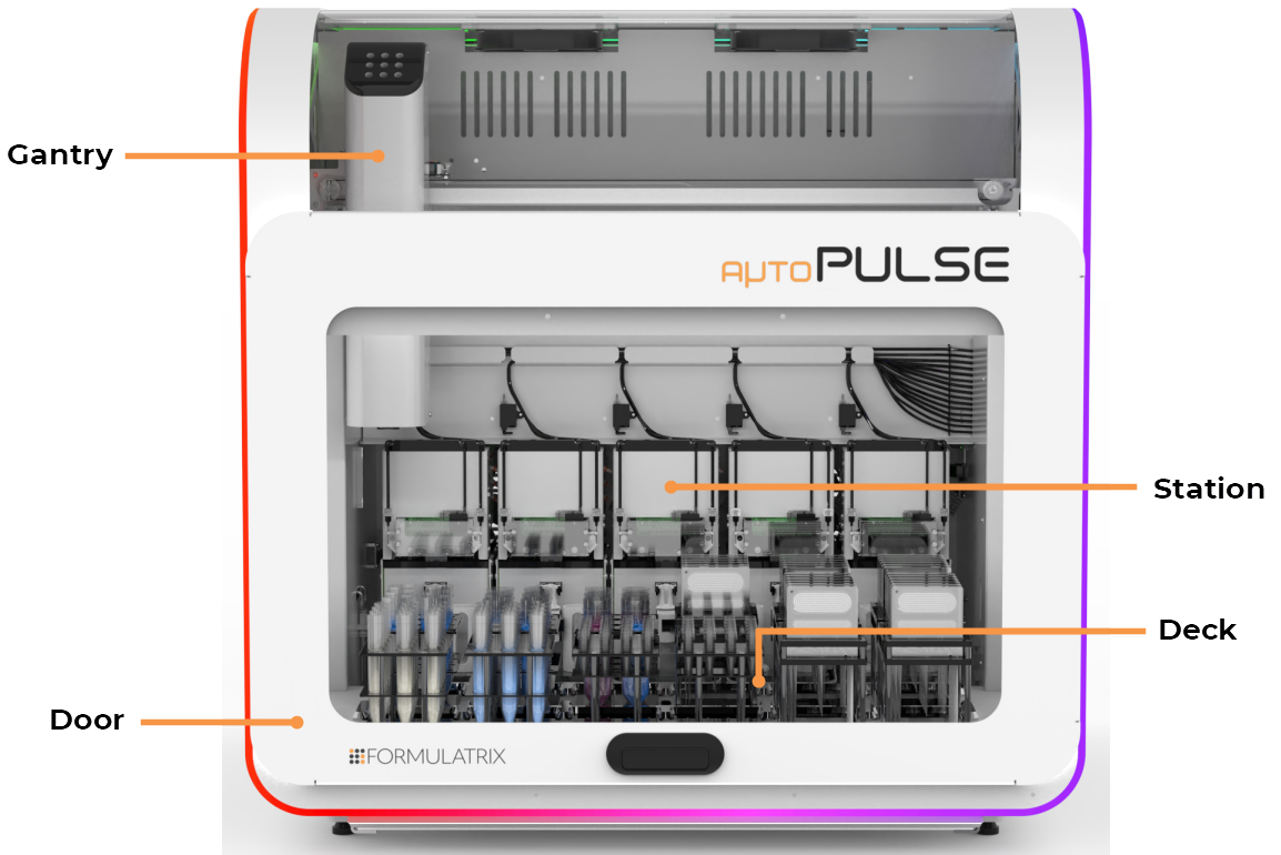
aµtoPULSE Front View
Door: Allows access to internal components and ensures safety during operation by remaining closed during active runs.
Gantry: Handles the movements of tubes and chips within the system to ensure proper alignment and station operation.
Station (as a whole unit): Integrates tubes, tube adapters, and chips during profile runs.
Deck: Holds up stations, racks, and all system components, providing the primary surface where operations occur.
Waste Tray: Collects any spilled liquid that occurs accidentally.
Important: If you find liquid in the tray due to a system error, check the source of the leak and contact support@formulatrix.com.
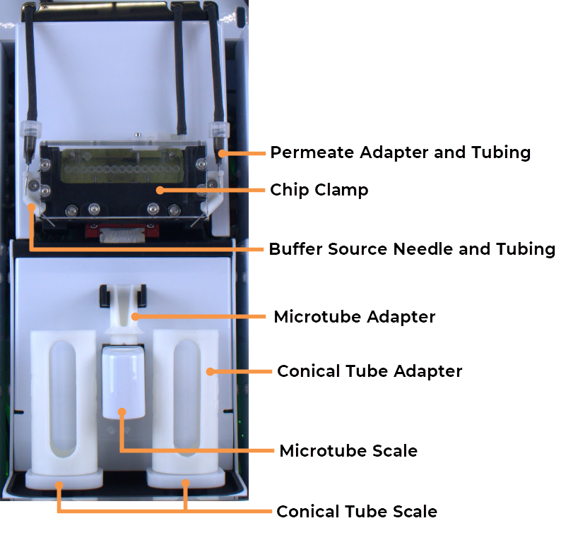
Station Components
Permeate Adapter and Tubing: Facilitates the transfer of permeate liquid.
Chip Clamp: Holds the chip securely in place during the operation to prevent any movement that could disrupt liquid flow.
Buffer Source Needle and Tubing: Delivers buffer liquid to the necessary components.
Tube Adapters: Couple the tubes to the instrument's balance pad. See the details below.
Microtube Scale: Measures the weight of small volume samples.
Conical tube Scale: Measures the weight of high-volume samples (50 and 15 mL).
The aµtoPULSE filtration chip is designed with several key components for high-performance filtration. Below are the primary components of the chip.
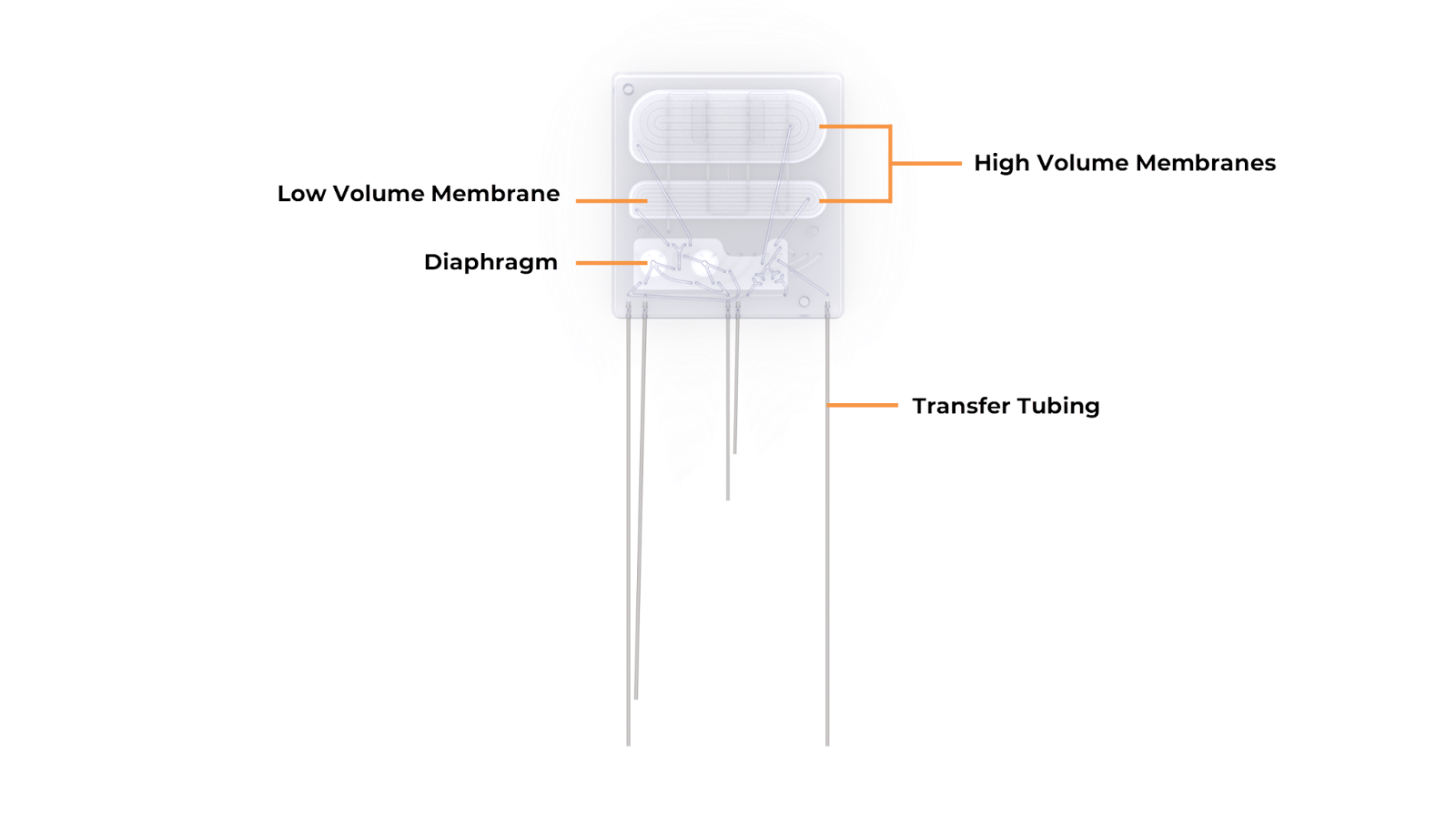
aµtoPULSE Chip Components
Membranes: The filtering element of the chip that separates the liquid into sample (retentate) and carrier reagent (permeate).
High-Volume Membranes: Process large volumes of liquid.
Low-Volume Membrane: Designed for smaller-volume filtration processes.
Diaphragm: Regulates pressure and flow within the chip, ensuring samples are transferred smoothly across the membranes.
Transfer Tubing: Connects to the chip for aspirating and returning the sample and/or buffer.
Open the aµtoPULSE software from your browser by typing: http://autopulse-[the device serial #]/.
E.g., http://autopulse-4/ for instrument AP-1-0004.
Enter your username and password to log in.
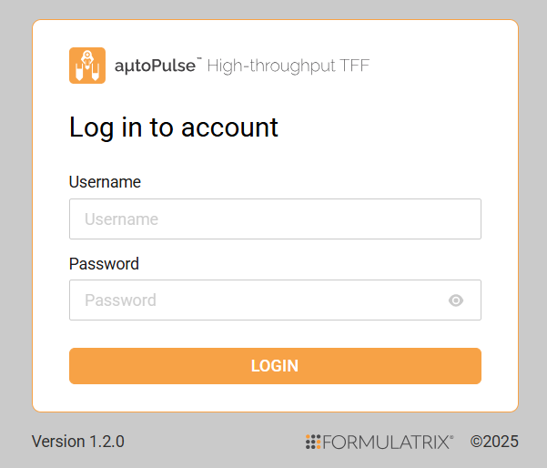
aµtoPULSE Software Login
You will interact with the system through several sections that include Explorer, Editor, Labware Manager, and Tools. Each section provides specific functionality for setting up and managing protocols, labware, and system performance.
The Explorer section is where you can manage protocols. In this area, you can view or open existing protocols, add a new protocol, search for a specific protocol, and sort the protocol names alphabetically (ascending or descending).
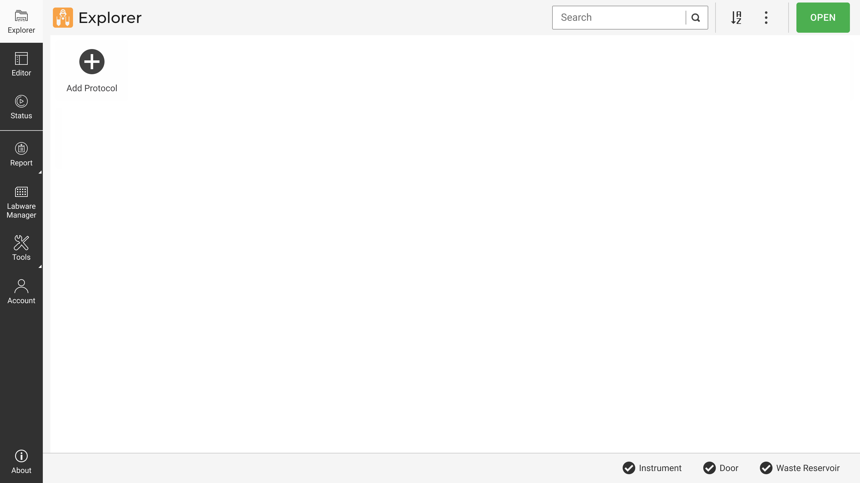
Explorer Page
In the Protocol Editor section, you can configure and modify the details of a selected protocol. There are four buttons on the Navigation Bar to provide additional functionalities for managing and refining protocols:
Import: Allows users to import existing protocol files, enabling quick setup or modification of pre-configured protocols. This feature is useful for reusing or sharing protocols across different projects or users.
Adv. Setup: Offers access to advanced configuration options, which allows you to define specific parameters or customize more complex protocol settings.
Profile: Provides access to create a new profile and adjust parameters related to the specific protocol being created.
Scan Adapters: Enables the automatic scanning of hardware components to ensure proper input in the software.
The layout includes a visual representation of the deck, divided into numbered slots where labware can be placed. You can go through the following tabs:
Labware: This section lists available labware and allows you to set up the stations with customizable components in the Station column such as tubes, tube adapters, buffer type, and volume. Go to the Deck column to define your preferred tubes and chips.
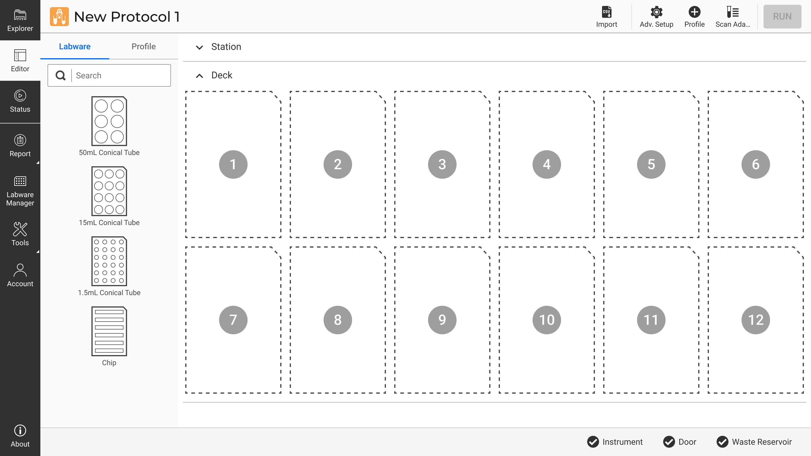
Labware Tab in Protocol Editor
Profile: You can view the number of profiles in progress and manage them by duplicating, removing, or editing profile details. Use the three dots next to each profile to duplicate or remove it. Click VIEW DETAILS to update your profile information.
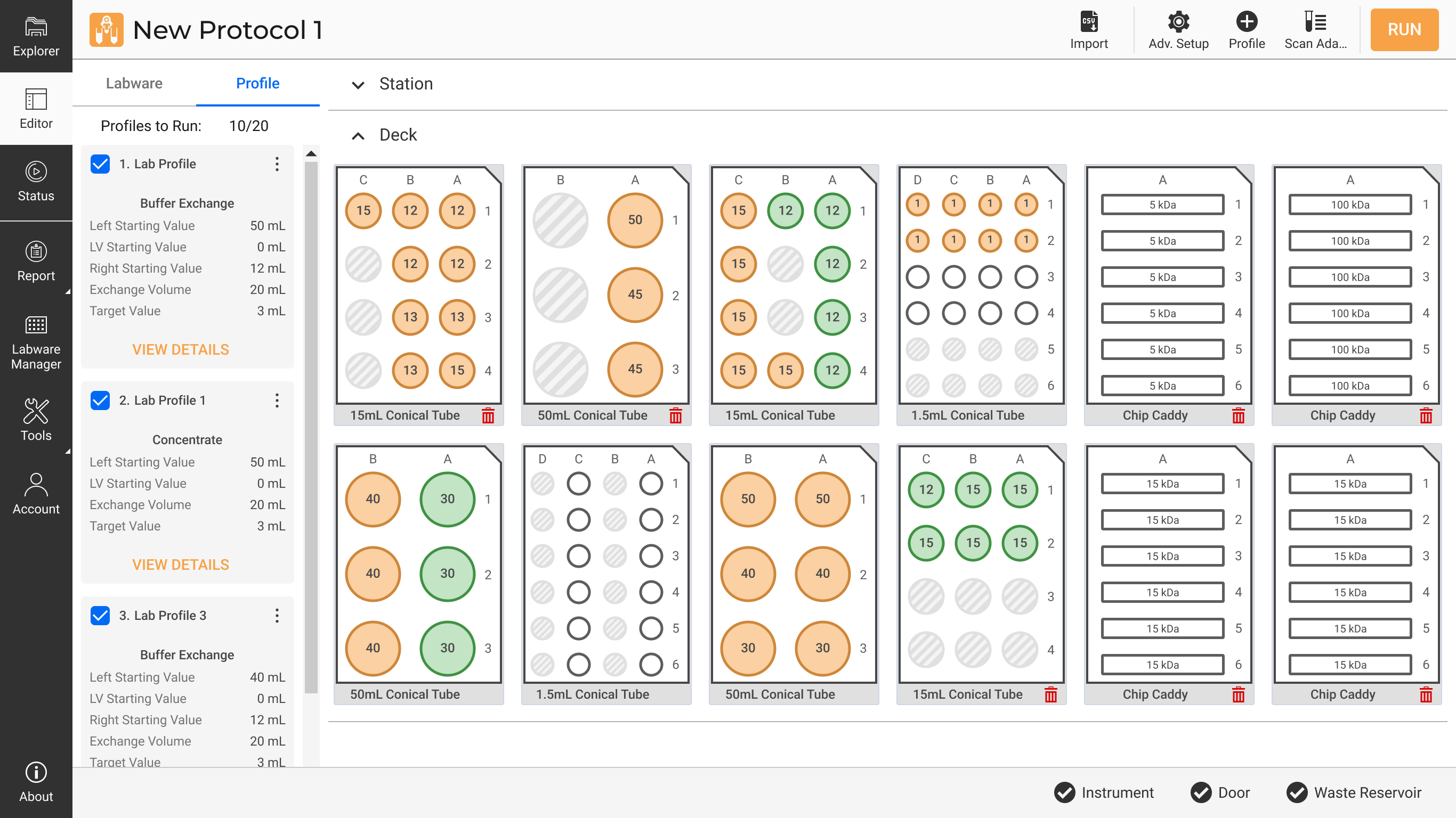
Profile Tab in Protocol Editor
The Labware Manager allows you to manage the labware, such as tubes and chips used in various protocols within the aµtoPULSE system. Each labware list includes:
Labware Name: Lists the available labware, such as conical tubes or chips, categorized by their size and configuration. For example, a "15mL Conical Tube 3x4" represents a set of 15 mL conical tubes arranged in a 3 by 4 configuration.
Labware Type: Displays the type of labware used, such as Tube or Chip.
Capacity (mL): Indicates the maximum volume the labware can hold. For example, "15" signifies a 15 mL conical tube, and "50" denotes a 50 mL conical tube.
Well Number: Refers to the number of wells or containers in the labware and the configuration. For instance, "12 (3x4)" represents 12 wells arranged in 3 rows and 4 columns.
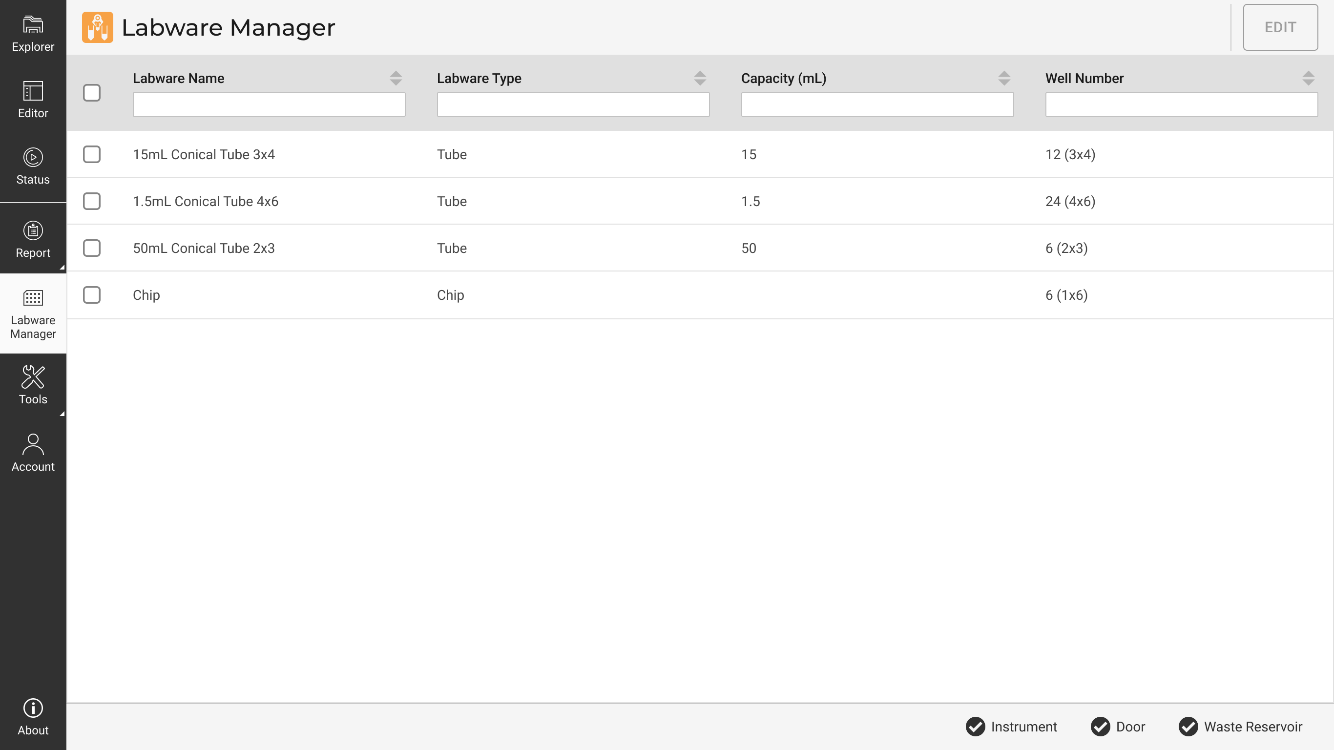
Labware Manager Page
The Labware Manager also enables you to customize labware settings based on the experimental needs. Select EDIT to rename labware or adjust capacity.
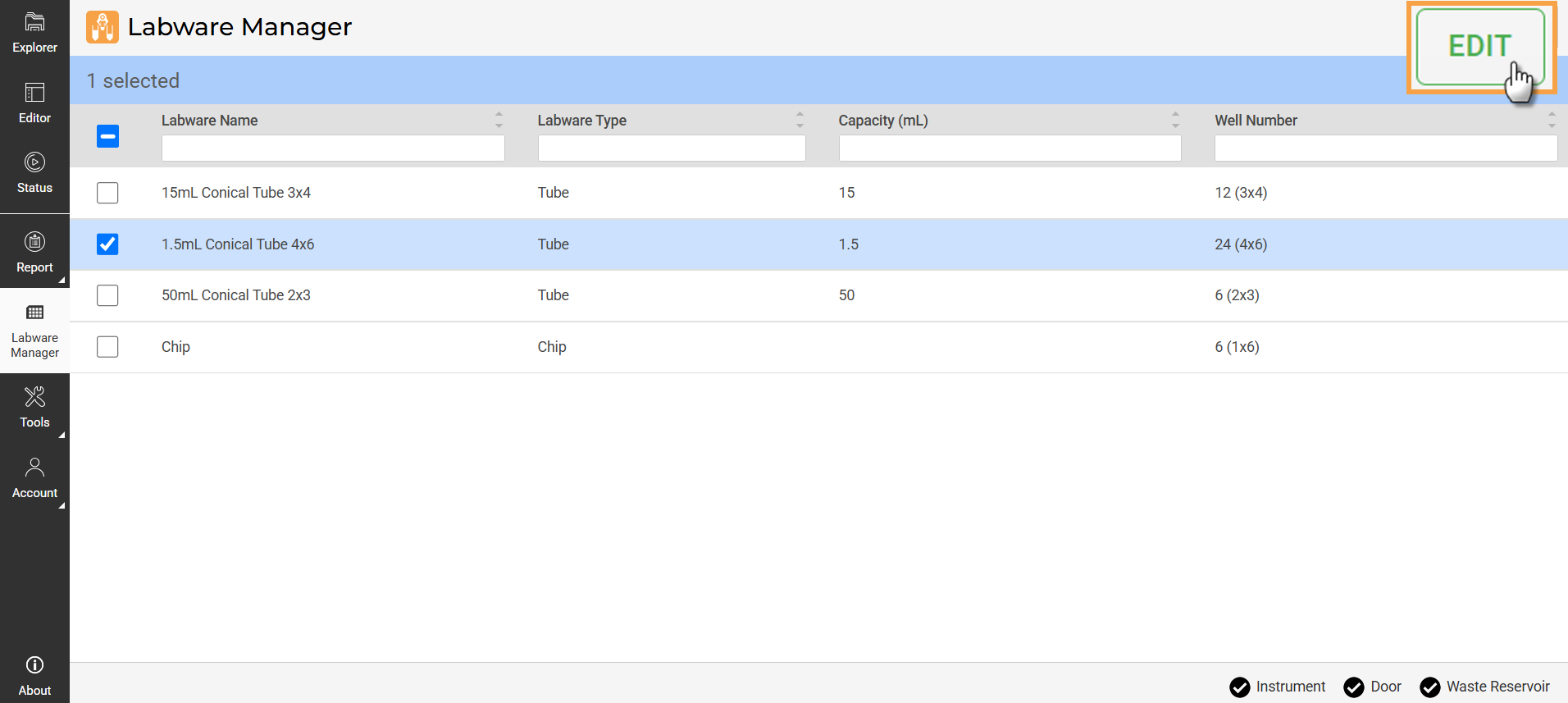
EDIT Button in Labware Manager
The Tools section provides advanced functionalities to enhance system control and customization. It includes:
Calibration: Calibrates scales and sensors to ensure accuracy in weight measurements, especially if there are differences or after long periods between calibrations.
Manual Control: Allows you to directly control specific components or stations within the system for testing or setup purposes.
Sequencer: You can manually create profiles here, offering flexibility to design and execute custom sequences for specific protocols or tasks.
Proper station setup is critical for ensuring the aµtoPULSE operates at its best. The steps below guide you through configuring the Concentration and Cleaning Stations, which are essential for processing your samples and ensuring system cleanliness.
The aµtoPULSE system comes with adapters for different tube sizes: 1.5 mL, 15 mL, and 50 mL.
Identify the tube size you plan to use: 1.5 mL, 15 mL, or 50 mL.
Select the adapter that matches your tube size.
Carefully install the selected tube adapter to the station.
Important: Make sure it is properly seated in the station to prevent any misalignment or operational errors during the protocol run.
The cleaning station in aµtoPULSE is an integral part of running a protocol. This ensures the chips are rinsed and free from contaminants before sample processing. You can go to the protocol creation process to configure the cleaning station settings, as the cleaning steps are embedded within the protocol. See Creating a Protocol to set up the cleaning station.
The buffer reservoir is a critical component that holds the buffer solution required for the concentration process. It must be adequately filled and maintained to ensure continuous operation. Monitor the liquid regularly to prevent any interruptions during sample processing.
The standard recommendation for cleaning is 0.1 M NaOH, but depending upon the application, different cleaning agents can be used. For example, if the only concern is sterility from bio-burden, the cleaning agent can be 10% NaClO or 3% H2O2. For protein removal, 0.1 M NaOH or even detergents can be used. But for detergents, you need to be cautious and should do thorough rinsing afterward. Other cleaning agents that can be used include:
Proper labware arrangement is essential for the efficient and safe operation of the aµtoPULSE system.
Here are some best practices to ensure optimal use of the deck area:
The Labware Rack Placement: Once the tubes are placed in the rack slots, ensure they are stable and aligned.
The Proximity of the Chip Rack to the Stations: Place the chip rack close to the concentration and cleaning stations. This setup minimizes the distance the chip needs to be moved, reducing the risk of any liquid dripping/spilling into the tubes during the transfer.
Regular Maintenance and Cleaning: Keep the deck surface clean and organized. Regularly inspect the area for spills or debris that could interfere with operations. A clean deck helps prevent contamination.
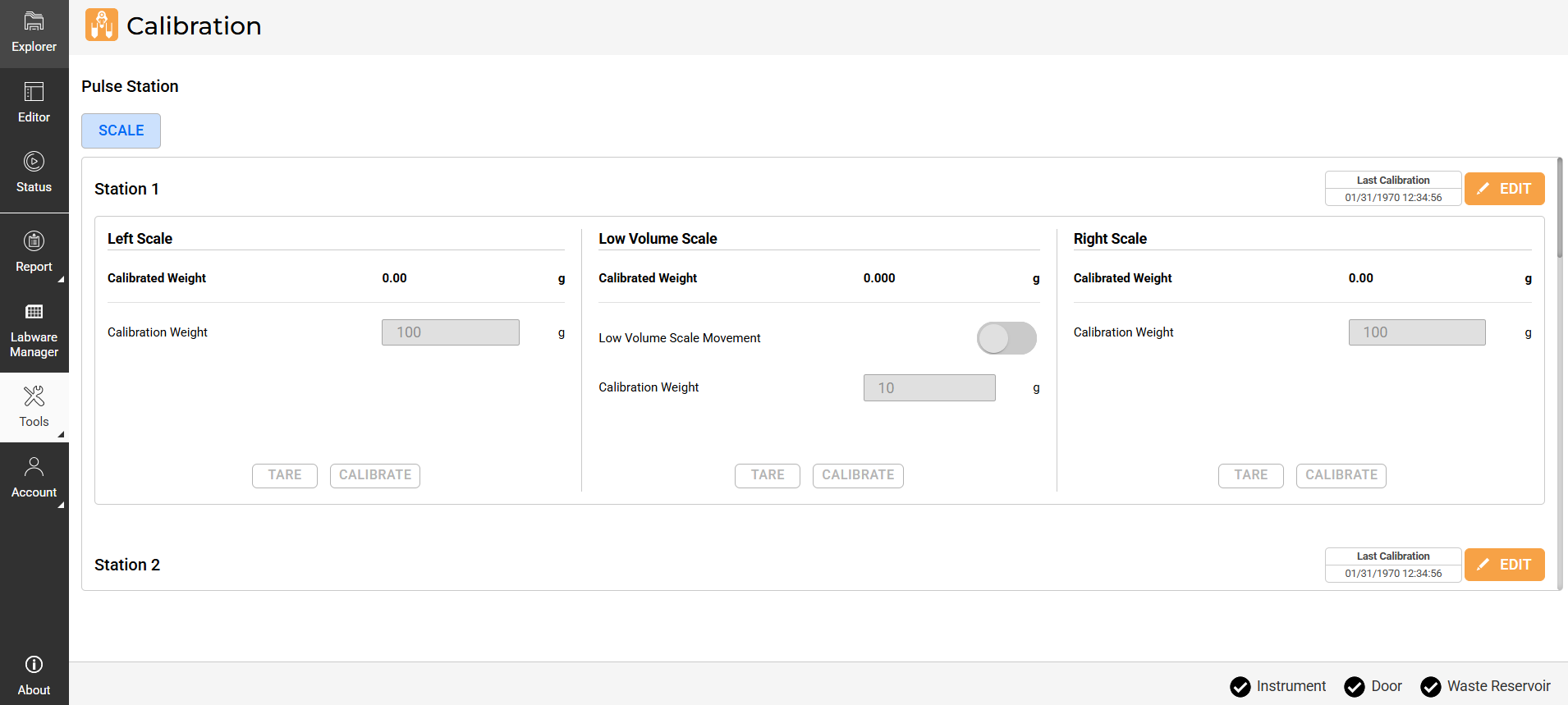
aµtoPULSE Station Calibration
The scales in aµtoPULSE require periodic calibration to ensure accurate measurements. You should take particular caution to recalibrate after the initial install, when transferring to a significantly different temperature, or when experiencing volume inaccuracy. Follow the steps below to calibrate the scales.
100 g calibration weight
10 g calibration weight
In the aµtoPULSE main menu, go to Tools and select Calibration. Then, go to the Station tab.
Each station is calibrated individually and has three scales: Left Scale, Low Volume Scale, and Right Scale.
Verify the Last Calibration time displayed in the upper-right corner of each station’s panel.

Last Calibration Time
If the last calibration was done over a week ago or if measurements seem inaccurate, click EDIT to start calibration.
Important! Make sure that there is no weight applied to both scales.
Do the following for each scale:
Left Scale and Right Scale
Click TARE to zero the scale.
Place the 100 g calibration weight on the center of the scale.
In the Calibration Weight field, enter the weight you are using to calibrate.
Click CALIBRATE to initiate the calibration process. The Calibrated Weight should match the calibration weight entered.
Repeat steps a-d for the other scale.
Low-Volume Scale
Activate the Low Volume Scale Movement toggle to lift the scale.
Click TARE to zero the scale.
Turn off the Low Volume Scale Movement toggle to lower the scale.
Place the 10 g calibration weight on the center of the scale.
Activate the Low Volume Scale Movement toggle to lift the scale.
In the Calibration Weight field, enter the weight you are using to calibrate.
Click CALIBRATE to initiate the calibration process. The Calibrated Weight should match the entered weight.
Turn off the Low Volume Scale Movement toggle to lower the scale.
Click the SAVE button  .
.
Repeat steps 3-6 for the remaining stations.
Note: The Cleaning Station(s) do not have a Low Volume Scale.
Creating a protocol is done in the aµtoPULSE software. It involves defining the station and deck that you have prepared and then creating profiles. Follow the instructions below thoroughly.
Open the aµtoPULSE software, and you will be directed to the Explorer page.

Explorer Page
Double-click the Add Protocol to access the Protocol Editor page.
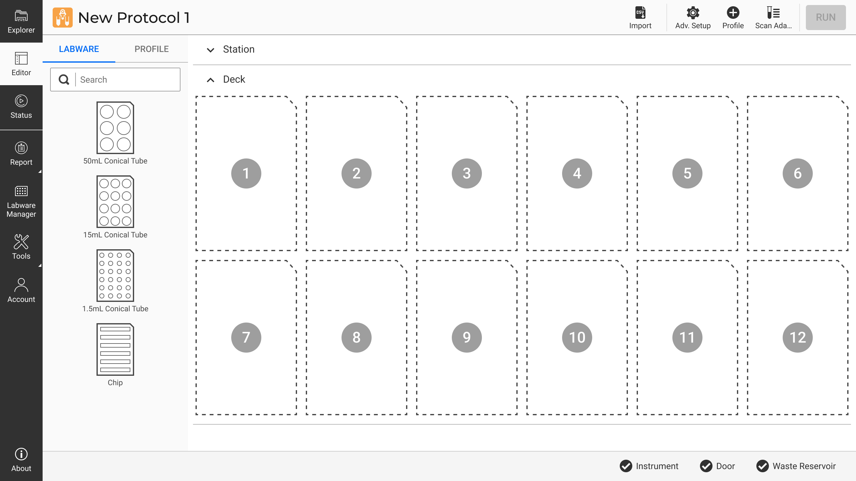
Protocol Editor Page
You can click the Import button to automatically create your protocol and proceed to Creating a Profile. Otherwise, you can manually define your protocol by continuing to step 4.
In the Labware tab, go to the Station column.
Note: Stations in gray represent Concentration Stations, while blue represents Cleaning Station(s).

Station Column in Labware Tab
If the stations are set up on the hardware, click the Scan Adapters button  on the Navigation Bar to configure them automatically. Otherwise, specify the following:
Concentration Station

Concentration Station Detail Information
Click APPLY to save the settings.
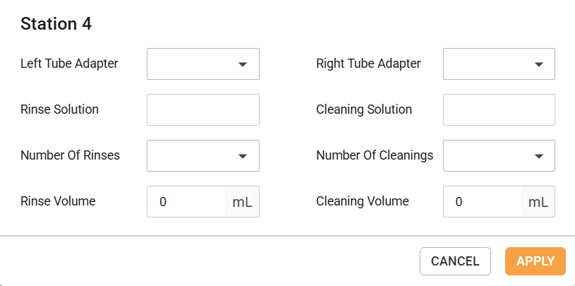
Cleaning Station Detail Information
Click APPLY to save the settings.
Note: If you have more than one Cleaning Station, only the Left Tube Adapter and Right Tube Adapter settings will need to be adjusted for the additional stations. All other parameters will be derived from the first Cleaning Station configuration.
Still in the Labware tab, navigate to the Deck column.
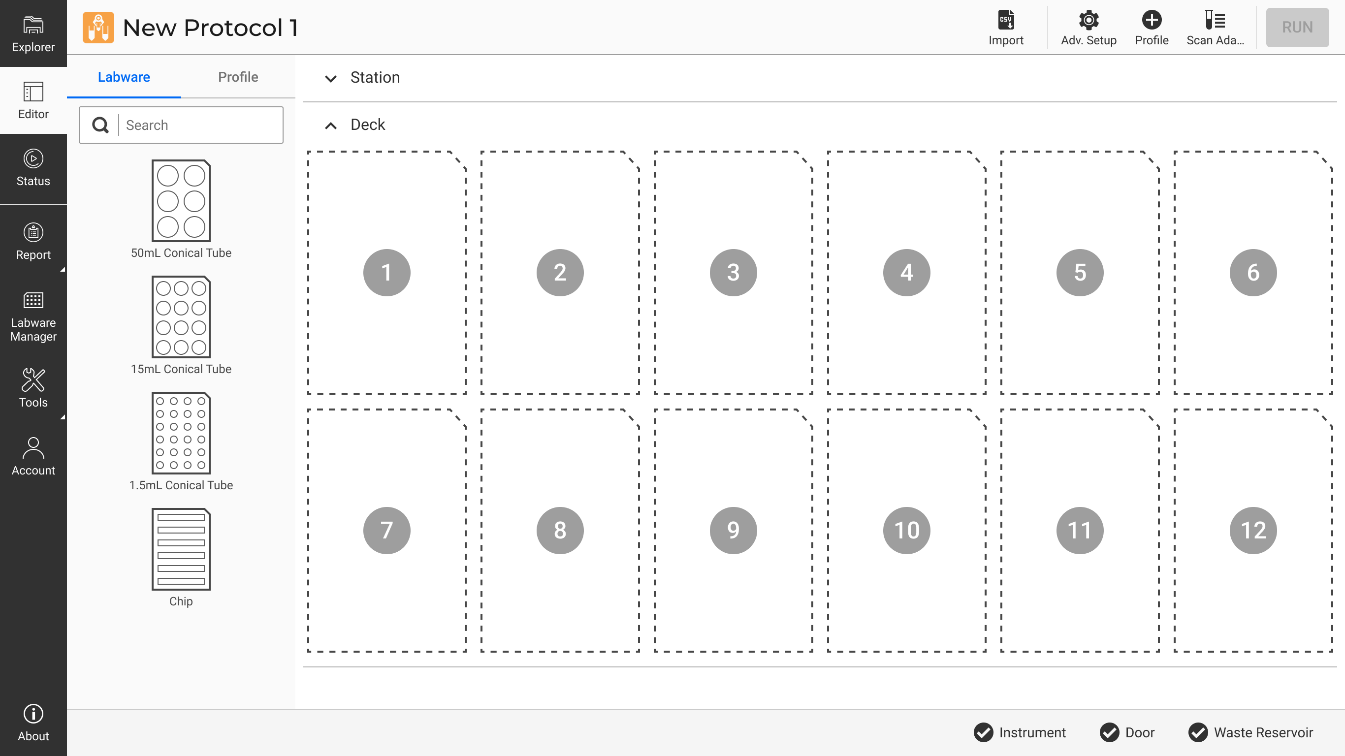
Deck Column in Labware Tab
Click on each of the wells to define the labware details.
Tube: If a tube is in place, activate the toggle, then fill in the Liquid Type, Starting Volume, Starting Concentration, and Density.
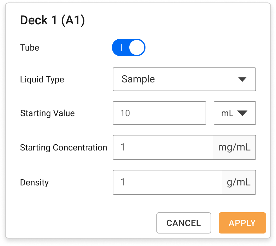
Tube Deck Detail Information
Chip: Select the MWCO if a chip is in place.
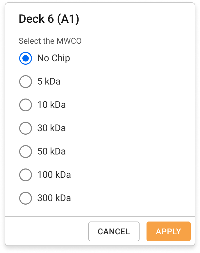
Chip Deck Detail Information
At the top right of the page, click the Profile button and set up the following:
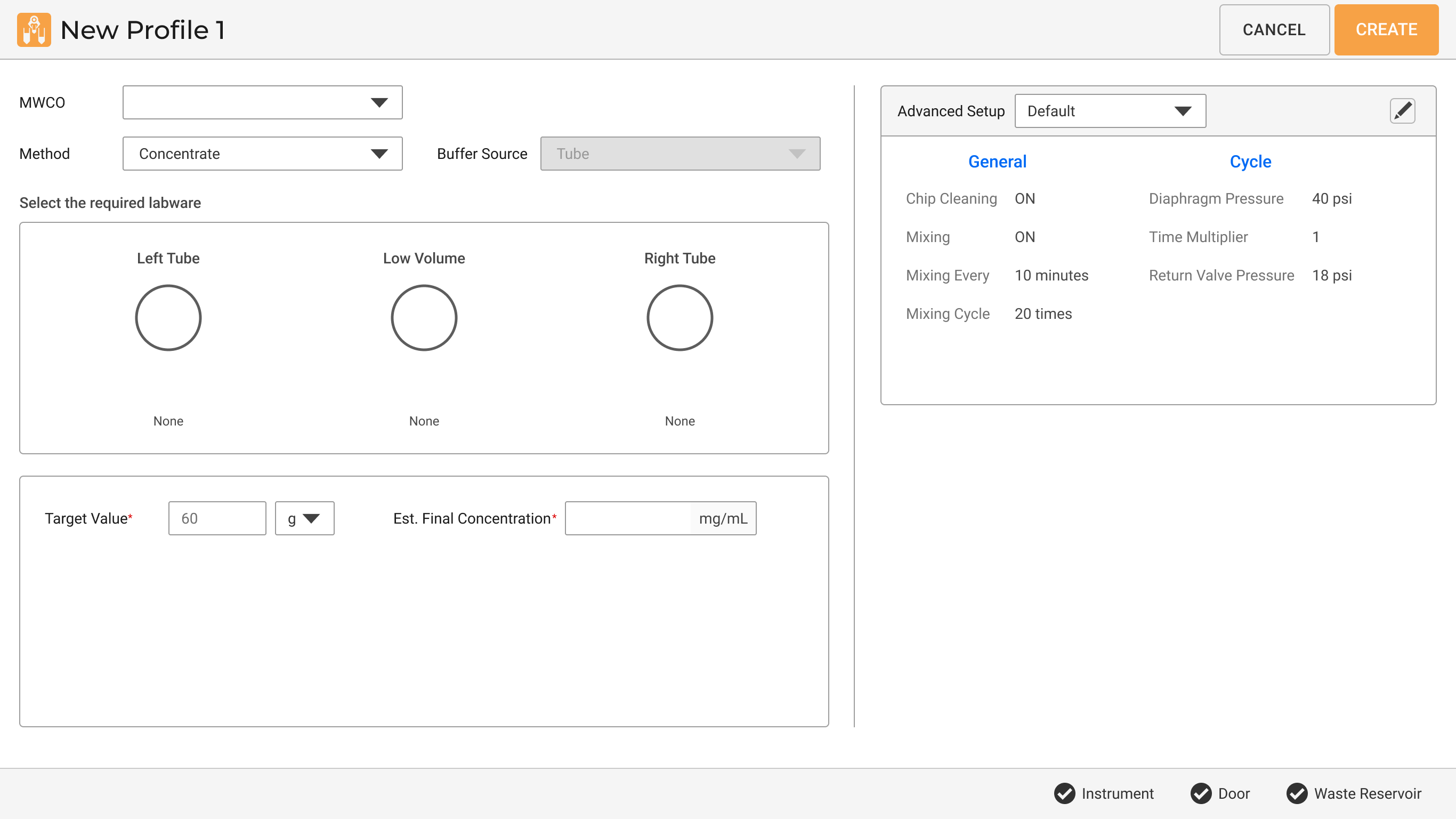
Creating a Profile
Select the MWCO size according to your preference.
Method: Choose Concentrate or Buffer Exchange. If you choose Buffer Exchange, define the Buffer Source from the provided options.
Note: You can still concentrate your sample with the Buffer Exchange method.
Select the required labware for each tube.
Fill in the Target Value, Start Exchange, Step Size, Est. Final Concentration, and Exchange Volume.
The system will use the default Advanced Setup.
OPTIONAL: Click the Edit button to customize additional settings.
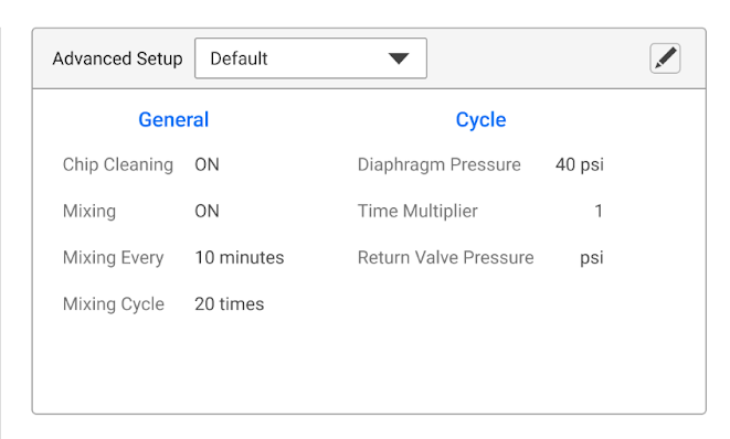
Advanced Setup Menu
Click CREATE to complete the protocol creation process.
Repeat step 1 to create more profiles.
You can duplicate or remove the created profile(s) by clicking on the three dots next to the profile name.
Your profile(s) will appear in the Profile list. Tick the checkbox on the profile(s) you wish to execute, then click RUN.
.png)
Click RUN to Execute Profile(s)
The aµtoPULSE Filtration Chips are rated for 300 mL of trans-membrane flow. Over-use of the chips can result in a loss of sample or damage to the device. For short-term reuse, chips must be stored wet in a sealed vessel. Long-term (>1 week) storage is not recommended without a bactericide. Follow the instructions below to store the chips properly.
Required Tool and Material:
To store the filter chip:
Put the chip inside the storage vessel to avoid solution leakage. Fill with enough water to completely submerge the chip.
Important: Leave the filter membranes wet and make sure the chips do not dry out. Otherwise, they will not function properly.
Seal and store the vessel in the refrigerator.
Label the stored chip with the total volume permeated. Note this volume for your chip's lifetime records. Dispose of the chip if the total volume permeated exceeds 300 mL, functionality of the chip beyond this can not be guaranteed.
To ensure durability and optimal performance, consider the chemical compatibility of materials used in the device. Some chemicals are safe for continuous use, while others can cause damage and should be avoided. Certain substances may only be suitable for limited use and require additional testing.

|
|
| APOWH-V12R125 |