You must calibrate the LC3 before initial use and whenever the MANTIS fails to pick up and return a chip from a chip station on the LC3.
LC3 calibration requires two processes, tuning the “locked” position and tuning the “unlocked” position. The “locked” position is the position of the chip when the MANTIS picks up a chip from a chip station. “Unlocked” refers to the chip position when the MANTIS returns the chip to the chip station.
-
Click Next.
-
In the first three steps of this wizard, you will configure the “locked” position of the chip. Stand up and look down at the MANTIS. Using the motion controls, align the edges of the metal MANTIS arm with the walls of the chip station.
-
Position the MANTIS hand so that the front point of the chip is directly above the front point of the chip pallet.
-
Use the motion controls to tweak the position of the arms and hand as necessary. Lower the hand into the chip station until the magnet picks up the chip, making sure that the arms remain parallel to the ground and are not flexed in an upward or downward position.
OR
You can also use the keyboard keys to control the motion:
-
W: The key moves the MANTIS arms backward along the Y Axis.
-
S: The key moves the MANTIS arms forward along the Y Axis.
-
A: The key moves the MANTIS arms left along the X Axis.
-
D: The key moves the MANTIS arms right along the X Axis.
-
R: The key moves the MANTIS arms upward along the Z Axis.
-
F: The key moves the MANTIS arms downward along the Z Axis.
-
Q: The key rotates the left carousel clockwise.
-
Z: The key rotates the left carousel counterclockwise.
-
E: The key rotates the right carousel clockwise.
-
C: The key rotates the right carousel counterclockwise.
-
You will now configure the “unlocked” position. Remove the chip from the chip pallet, and attach it to the MANTIS hand.
-
Align the metal MANTIS arm with the walls of the chip station. Then, position the hand above the chip station, this time aligning the tabs on the chip pallet with the indents at the edge of the chip station.
-
Lower the chip into the chip station, being careful to keep the arms of the MANTIS parallel with the ground. If the position is correct, the MANTIS will leave the chip in the chip station.
-
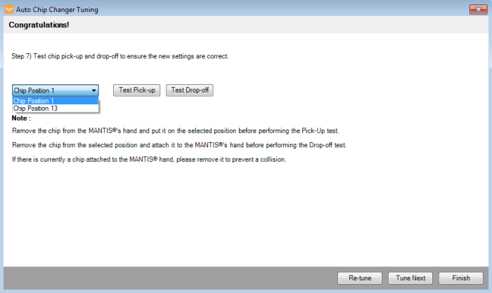
Test pick-up and drop-off for both chip positions to ensure the new settings are correct.

Test the Chip Position Settings
Note: If you have the 18 chip carousel, you can test for position 1 and position 10. If you have the 24 chip carousel, you can test for position 1 and position 13.
-
If you are satisfied, click Finish. Otherwise, click Re-tune to re-tune the chip positions.
-
Optional: Click Tune Next to tune pick-up and drop-off positions for another carousel.
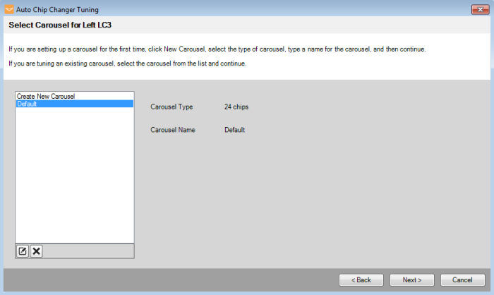
 to change a carousel name, and click the Delete button
  to remove an existing carousel from the list.

