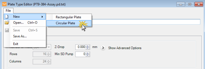
On the Tools menu, click Plate Type Editor.
Go to the File menu, point to New, and then select Circular Plate.

Adding a Circular Plate
Note: You can use the keyboard keys to control the MANTIS arms motion when adding or modifying plate types.
W: The key moves the MANTIS arms backward along the Y Axis.
S: The key moves the MANTIS arms forward along the Y Axis.
A: The key moves the MANTIS arms left along the X Axis.
D: The key moves the MANTIS arms right along the X Axis.
R: The key moves the MANTIS arms upward along the Z Axis.
F: The key moves the MANTIS arms downward along the Z Axis.
On the Tools menu, click Plate Type Editor.
Go to the File menu, point to New, and then select Circular Plate.

Adding a Circular Plate
Click the Lock Plate Clamp button 
Place your circular plate with the plate adapter on the MANTIS plate holder.
Type the name of your plate in the Plate Type Name.
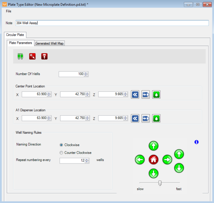
On the Plate Parameters tab, select the number of wells your plate contains from the Number of Wells list.

Plate Parameters Tab
To set the plate's center point:
Optional: Click and hold the Manual Prime button  until the chip begins dispensing drops.
Type the Center Point Location of the X, Y, and Z axis in the available boxes. Then, click the Move to Specified Center Position button  to check the location.
Use the Motion Control Pad at the lower right of the Plate Type Editor to modify the A1 well position. Use the arrow keys to maneuver the MANTIS hand to the A1 location of your plate. View the plate from both the side and the front to ensure your center location is correct. View the plate from both the side and the front to ensure your center location is correct.
Click the Set Current Position as A1 button  once you are satisfied with the position.
Click the Test Dispense on Center On A1 button 
To set the A1 dispense location:
Optional: Click and hold the Manual Prime button  until the chip begins dispensing drops.
Type the A1 Dispense Location of the X, Y, and Z axis in the available boxes. Then, click the Move to Specified Center Position button  .
.
Use the Motion Control Pad at the lower right of the Plate Type Editor to modify the A1 well position. Use the arrow keys to maneuver the MANTIS hand to the A1 location of your plate. View the plate from both the side and the front to ensure your center location is correct. View the plate from both the side and the front to ensure your center location is correct.
Select either Clockwise or Counter Clockwise as the direction you would like the MANTIS to dispense around the plate.
Set the well naming convention by typing a number in the Repeat numbering every wells box. For example, if you type ‘6’, then the MANTIS will name the first well A1, and after well A6 it will start naming wells with B1 until B6, and so on.
Check the MANTIS dispense location settings: Go to the Generated Well Map tab, and then click Move to Position button. The MANTIS will move its arms to the related location. If the locations are inaccurate, repeat steps 7 through 11. Otherwise, proceed to step 12.
_700x661.png)
Dispense Location Map (Generated)
Go to the File menu in the Plate Type Editor window, click Save As, type a name for your plate, and click Save.
OR
Go to the File menu in the Plate Type Editor window, click Save (Ctrl+S) to save your changes.

|
|
| MAOWH-V47R722 |