Defining Default Imaging Settings
The Default Imaging Settings sub-menu is where you define the default optics and camera settings to use when imaging a certain plate type.
Upon installation, the FORMULATRIX support team will configure the properties for optimal image quality and performance. If you need to add a new plate type to your imager, then please contact support@formulatrix.com for help. We recommend that only advanced users modify these settings. The information below is for lab managers so that they may adjust settings as they see fit.
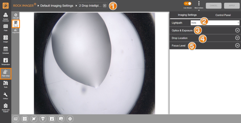
Default Imaging Settings Sub-menu
Note: The Control Panel is available next to the Imaging Settings panel so you can easily navigate between the wells, zoom in and out of the drops, and adjust the camera and optics settings without having to go to the Imager menu.
|
Item |
Description |
|---|---|

Plate Type List |
Select the plate type you are interested in editing. You can add new plate types to the list from ROCK MAKER software. You can export new plate type definitions by clicking More Actions and selecting Export. The system will save your plate type settings in an .XML file format. You can also use the Import feature to import the file later if needed or if you obtain new plate type settings from FORMULATRIX support. |

Lightpath |
Select the lightpath of interest. The type of imaging modes available here depends on the imaging types you purchased. The Visible lightpath is the default imaging setting and is always present. Each lightpath provides slightly different settings for area numbers 3, 4, and 5. If you select Ultraviolet, the Enable For This Plate Type option will show up. Enabling this option allows you to image your experiments using UV lightpath. |

Optics and Exposure |
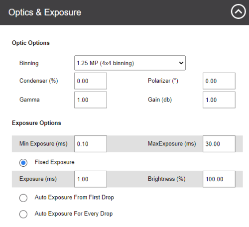
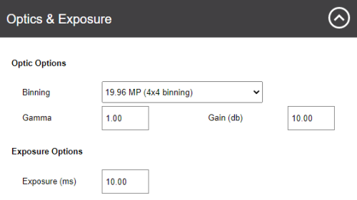
This area contains settings for the optics components and resolutions along with the exposure settings to use during plate imaging. Optics & Exposure Options for Visible Lightpath Optics & Exposure Options for Ultraviolet Lightpath
|

Drop Location |
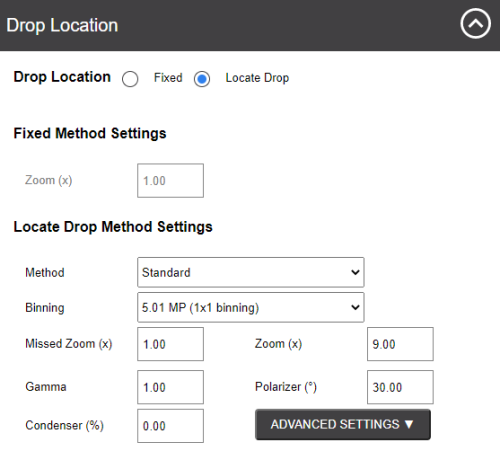
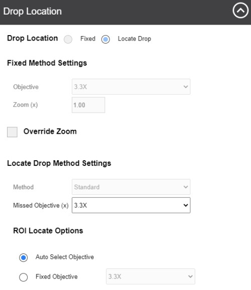
Drop Location settings determine how ROCK IMAGER® executes the Drop Location algorithm for the selected plate type. Options may vary depending on the imaging methods you purchased. Drop Location Options for Visible Lightpath Drop Location Options for Ultraviolet Lightpath ROCK IMAGER® can execute Drop Location in two ways: Fixed method and Locate Drop method.
Locate Drop Method Settings When using the Locate Drop method, you can further customize how to run the Drop Location algorithm. Locate Drop Method Settings From the Method box, you can choose between Standard and Lipidic Cubic Phase (LCP). The LCP method instructs ROCK IMAGER® on how to locate drops on an LCP or glass plate. The other fields determine the optics and camera settings used while the system is locating a drop before imaging.
|

|
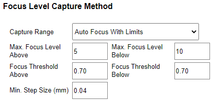
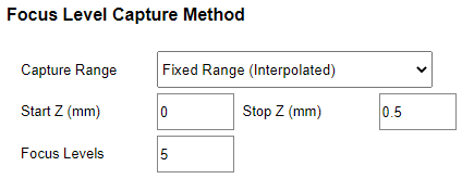
Think of Focus Level as a capture range. These settings dictate how the system images a drop once it locates one and adjust the number of focus levels acquired. You can select Auto Focus with Limits, Fixed Range (DoF Limited), or Fixed Range (Interpolated).
Runs the Auto Focus algorithm on the drop to pinpoint the best focus level for the drop on the Z axis. Once the focus level is determined, the system captures images above and below this point, called “slices”. The slices are analyzed and compiled by ROCK IMAGER Processor into Extended Focus Image (EFI), which is the default image displayed in ROCK MAKER. Note: Auto Focus with Limits is used when the Z position of the drop is inconsistent across the plate. This can be used for LCP and hanging drop experiments. Auto Focus with Limits There are five settings that dictate how slices are acquired:
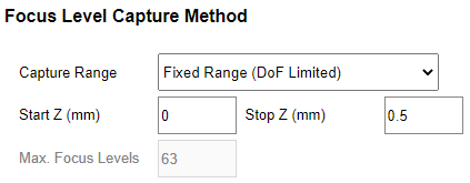
Fixed Range (DoF Limited)
Using this option, ROCK IMAGER® will capture slices along the Z axis between the start and stop heights and also determine the best number of slices to take based on the Depth of Field (DOF) of the optics in use. Fixed Range (DoF Limited) The three settings below the Capture Range box dictate how slices are captured. The Start Z (mm) and Stop Z (mm) values determine the range along the Z axis where the system captures slices of the drop. The Max. Focus Levels value equates to how many slices ROCK IMAGER® captures before sending the images to RIP.
Capture Levels
Auto Focus Capture Range Available for Visible light path only. This setting limits the movement of Auto Focus (in mm) with the default values for the Auto Focus Range between 0 - 0.5 mm. You can change these values by typing your desired values into the corresponding boxes. |

|
|
| RIOWH-V41R023 |
