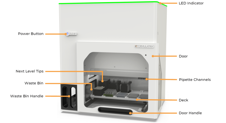
Before setting up the FLO i8 instrument, review component names and locations.

FLO i8 Front View
The LED indicator glows various colors, each indicating a different instrument status during software operation:
| Color | Description |
|---|---|
| Blue | Initializing, this may take a minute or two. |
| Multi-color | System is idle. |
| Green | Busy or running a protocol. |
| Yellow | Paused during protocol execution. |
| Red | An error has occurred. |
The power button turns the FLO i8 instrument on and off. This button glows various colors to indicate different statuses:
| Color | Description |
|
Red (Blinking) |
The instrument is connected to the power source and powering up. At this stage, you can press the button and wait until the instrument initializes. |
|
Red (Solid)* |
The instrument has been powered up and is ready for initialization. You can press the button to activate the instrument. |
|
Green (Blinking) |
The instrument is initializing or shutting down. It may take a few seconds. |
|
Green (Solid)* |
The instrument is active and ready to connect with the software. Refer to the LED indicator for the software status. |
|
Multicolor (Fast-blinking) |
An unrecoverable error has occurred. Please contact FORMULATRIX support by emailing support@formulatrix.com to get technical assistance. |
*See the Getting Started with FLO i8 for more information on how to turn on the instrument.
The transparent door keeps the deck and labware safe. You can easily see through the door to monitor what is happening on the deck.
Note: For safety reasons, the FLO i8 instrument will automatically pause when the door is open. Before pausing, FLO i8 will finish any ongoing task, after which the deck will be automatically moved toward the user. The protocol will not resume until you close the door.
There are three types of FLO i8 Next Level Tips® pipette tips:
These pipette tips come with filters and are PCR-Grade (tested RNAse-free).

|

|

|
| F20 | F200 | F1000 |
The Next Level Tips® are packed in a tip box that holds 96 pipette tips.
The waste bin is located at the left side of the deck, where the FLO i8 disposes of used tips. To prevent the tips from being piled up in the middle, magnetic waste feet are installed above the bin. This component evenly distributes the used tips to maximize the waste bin space. Make sure to empty the waste bin when it is full. Pull the waste bin door to remove the used pipette tips from the waste bin.
You can find the ID tag on the inner-right side of the waste bin. It includes the instrument’s serial number, voltage, frequency, max power, build date, and CE marking.
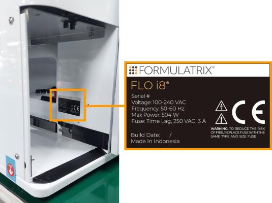
Instrument’s ID Tag Inside the Waste Bin
There are 8 Pipette Channels that handle the liquid aspiration and dispense processes. The nozzle at the end of each channel interfaces with the disposable pipette tips, maintaining an airtight seal.
The rightmost channel is equipped with a vision camera. There are also four sensing systems on each channel: the Pressure, Resistance, Collision, and Liquid Breach Sensors.
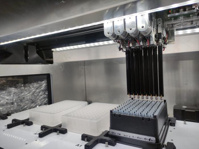
The 8 Pipette Channels in FLO i8
The FLO i8 deck holds everything you need to run an experiment, including labware and tips. The deck consists of 10 slots that will securely hold the tip box and plates that you want to use, with a maximum height of 140 mm. Each slot is compatible with almost all Society for Biomolecular Screening (SBS) standardized labware types. The FLO i8 also provides 3 adaptor racks for 1.5, 15, and 50 mL conical tubes.
The deck is also equipped with deck markers located on each slot to facilitate the vision camera on the rightmost channel. This camera automatically detects any labware or tip box on the deck. Each deck marker has a unique pattern to differentiate one slot to another. This way, FLO i8 channels will only dispense thoroughly to the available labwares based on your experiment design.
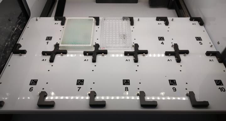
FLO i8 Deck with Deck Markers
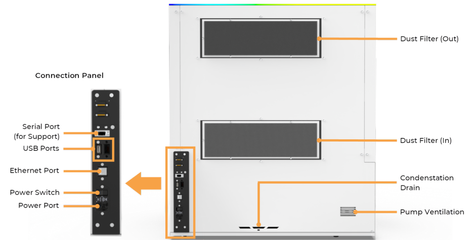
FLO i8 Back View
The dust filter removes particulates from the air entering the system.
Some condensation might occur in the pressure and vacuum reservoirs inside the FLO i8 instrument during operation. The condensation drain collects the moisture and allows it to evaporate without harming the instrument.
The pump ventilation releases the heat and airflow generated by the pressure and vacuum pumps.
The connection panel consists of the following components:

|
|
| FLOWH-V27R124
|
Unit 6, Level 13, Gate District, Gate Building Dubai International Financial Centre |