Before you set up the PULSE hardware, you’ll need to understand the names of its components and where each component is located on the system.

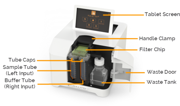
PULSE - Front View
The tablet screen is where you can interact with PULSE. Here you can control the instrument, create and run your experiments, and so on.
The handle clamp securely holds the chip in place over the tube mount.
The PULSE filter chips come with six membrane cutoff sizes: 3, 5, 10, 30, 50, and 100 kDa. Filter chips can be purchased from the FORMULATRIX online store at https://formulatrix.com/accessories/. See also, Chip Overview.
The waste slide transfers waste liquids from the chip to the waste tank.
The PULSE waste door keeps the waste tank safe. You can easily check the waste tank capacity through the window in the waste door.
The waste tank is used to deposit waste liquids from the chip. The waste tank can hold up to 125 mL of liquid.
The tube caps connect the chip to the liquid tubes, and can be used with any common 50 mL tube. They are identical so they can be used for either sample or buffer solutions. The caps should be washed after each use.
The left input of the PULSE is for the sample tube, and the right input is for the buffer tube. Any common 50 mL tube will work with PULSE.

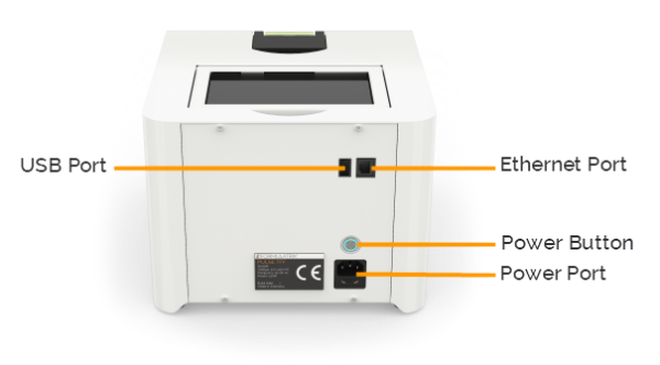
PULSE - Back View
The Ethernet port is used to connect the PULSE instrument to the Internet through a wired network, so that you can update the PULSE software.
The USB port is used for updating the PULSE software manually if an Internet connection is not available. It may also be used by support for debugging or troubleshooting purposes.
The power button turns the PULSE instrument On or Off. Before turning the instrument off you should shut down the system by tapping the SHUTDOWN button on the PULSE software home screen. Turning off the PULSE hardware without first shutting down the system could damage the system’s firmware.
The power port is where you plug in the power cable. See also, Electrical Requirements.
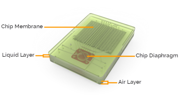
PULSE - TFF System filter chips come with six membrane cutoff sizes: 3, 5, 10, 30, 50, and 100 kDa.

Filter Chip Overview
Each filter chip consists of the following components:
Membrane: The membrane is what separates the sample (permeate) from its carrier reagent (retentate).
Diaphragm: The diaphragm helps the liquid flow through the filter chip.
Liquid Layer: The liquid layer is the channels through which the liquid flows.
Air Layer: The air layer is the channels through which air flows to actuate the diaphragm.
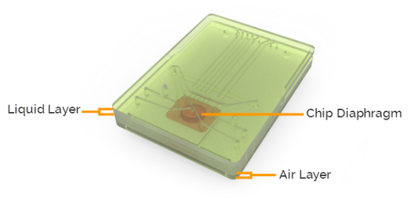
PULSE - TFF cleaning chip is exclusively used for cleaning the tubing.

Cleaning Chip Overview
Each cleaning chip consists of the following components:
Diaphragm: The diaphragm helps the liquid flow through the filter chip.
Liquid Layer: The liquid layer is the channels through which the liquid flows.
Air Layer: The air layer is the channels through which air flows to actuate the diaphragm.
 | |
| PTFF-V1.2R019 |