_800x431.png)
A plate definition contains settings (such as drop positions coordinates and optics controls) that determine how the ROCK IMAGER captures drop images on a plate. Several plate definitions come packaged with the ROCK IMAGER for your convenience, but you may need to set up additional plate definitions depending on the plate types you use. When setting up a plate definition, you will need to configure some important settings such as X, Y, and Z coordinates for the four corner well locations (i.e. top-left, top-right, bottom-right, and bottom-left). You can always contact support@formulatrix.com for help in setting up plate definitions.
You have created an experiment in ROCK MAKER. If you aren’t interested in tracking conditions with ROCK MAKER, you can create a proxy experiment.
Your plate has a barcode label affixed to the short side of the plate opposite the A1 position.
You have tuned the reference plate.
Power-on the ROCK IMAGER hardware and run the ROCK IMAGER software.
Load the plate type into ROCK IMAGER, scan the barcode, and then position the plate on the imager hand. The Plate should be inserted with the barcode facing away from you.
On the File menu, click Plate Type Editor. Make sure that Well Limits is set to Disabled and leave the Plate Type Editor open.
Note: Do not click Apply or OK in the Plate Type Editor menu at this time.
_800x431.png)
ROCK IMAGER 1000 Plate Type Editor
Under the Drop Positions, calibrate the X, Y, and Z coordinates for the four corner well locations accordingly.
Select a Drop from the Drop list. If your plate has multiple drops per well, make sure to select the correct drop that corresponds with the drop you are currently viewing in ROCK IMAGER. You must calibrate every drop for each of the four corner wells.
On the Imager menu, select Crosshairs.
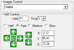
On the main ROCK IMAGER software window, go to the Well Control panel, and select one of the speed options (Fast, Medium, or Slow).

Well Control Panel
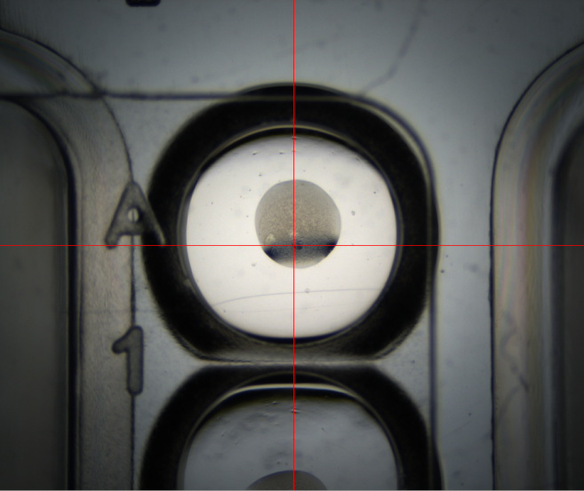
Use the arrow buttons on the Well Control panel to move the imager to the first well location (such as Well A1) and adjust its positions. Move the crosshairs to the center of the well and use the Z axis control arrow buttons (located to the right) to focus the drop image. You can also adjust the zoom if necessary in the Optics Control panel. (see the image sample below).

Drop A1
Return to the Plate Type Editor window, and click the  button next to the well location to copy the coordinates.
Repeat steps d-e for configuring the other three corner wells of the plate.
Verify the well positions.
Return to the Imager tab.
Under the Well Control, select Well, type a well location in the Well box (such as A1), and choose a Drop option from the corresponding list.
Click the C button. ROCK IMAGER should display the center of the selected well drop. You can move to the next well drop by clicking the arrow buttons on the well control pad.
Return to the Plate Type Editor window. Specify the Drop Location and the Method that you would like to use. Fixed Drop Location should be used for drops that are centered in the well with consistent relative positions. This method will have the fastest imaging time and is recommended for routine sitting drop experiments. Standard Drop Location should be used for soluble protein experiments and is useful for plates where the drop position is not consistent and the size of the drops are small relative to the well area.
When done, click Apply.
Click the Export to File button in the lower left corner of the Plate Type Editor window, and then browse the desired location to save your new plate definition.

|
|
| RIC-V38R119 |