SLP UV Optics Controls

Optics Controls allow you to manipulate the microscope's optics while manually inspecting a plate. The optics controls appear on the left-hand of the Live Image Sub-Tab of the Imager Tab, and vary based on the imaging methods you purchased.
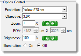
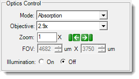
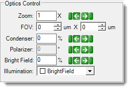
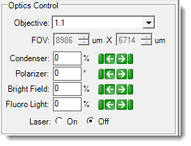
There are seven possible optics control panels, as shown below.
Fluorescence Optics Controls

|
UV Optics Controls
|
Visible Light Optics Control

|
|
| FRAP Optics Controls
|
SONICC Optics Controls
|
SLP Visible Optics Controls

|
|
|
SLP UV Optics Controls  |
Use the table below to learn about the various controls and what effects they have on the resulting live image.
| Control | Imaging Methods | Description | Notes |
|---|---|---|---|
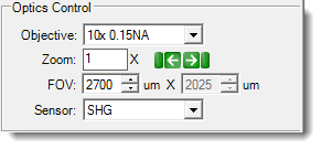
| Excitation | ▶ Fluorescence | The Excitation list provides you with three different light wavelengths. The standard package includes Ultraviolet 290 nm, Visible Fluorescence 485 nm, and Visible Fluorescence 578 nm. | Available Excitation list depends on the filter modules you purchased. |
| Mode | ▶ UV | The Mode list provides you with two UV imaging options, including Absorption and Fluorescence. | UV absorption imaging is available to new ROCK IMAGER 1000 models only. |
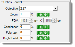
| Objective | ▶ SLP Visible ▶ UV ▶ Fluorescence ▶ FRAP ▶ SONICC |
To change the Objective values, click the corresponding list, and then select the desired value as necessary. | |
| Zoom | ▶ Visible ▶ SLP Visible ▶ UV ▶ Fluorescence ▶ SONICC |
The Zoom field is generated by the current zoom setting and is related to the FOV field. These fields allow you to zoom in on regions of interest within a drop or well. To change the Zoom values, type a new value in the corresponding box, and press Enter on your keyboard. Alternatively, click the left and right arrows to decrease or increase the values. |
Available zoom settings depend on the options you purchased. In most cases the zoom selection will cause a mechanical change in the lens, which produces the desired zoom. Digital zoom with fixed objectives is available in all ROCK IMAGERs with nine megapixel cameras. In SONICC, changing the zoom value changes the laser beam scan angle. In MFI, the Zoom field controls the continuous zoom, which is achieved by cropping the images captured by the camera. The FOV for fluorescent images will match the FOV for visible images, which also enhances the viewing of images in ROCK MAKER. |
| Field of View (FOV) | ▶ Visible ▶ SLP Visible ▶ UV ▶ Fluorescence ▶ FRAP ▶ SONICC |
You can use the FOV fields to manually set the size, in µm, of the image you would like to view. As you change the FOV value using either the text entry field or the arrows, the zoom value automatically adjusts. | |
| Sensor | ▶ SONICC | The Sensor selection determines whether you are using SHG or UV-TPEF. | The SHG imaging method images the sample with IR and detects the SHG (532 nm) in transmission. Signal is only generated from chiral crystals. The UV-TPEF imaging method images the sample with green light (532 nm) and detects the two photon fluorescence generated (350-400 nm). Signal is generated from UV-fluorescent molecules like tryptophan. |
| Brightness | ▶ Fluorescence | The Brightness values range from 0% - 100%. For imaging with ROCK IMAGER 1000 and ROCK IMAGER 2 MFI, set the Brightness to 100% as a starting point. | |
| Illumination | ▶ Visible ▶ UV ▶ SLP UV ▶ Fluorescence |
On the visible imaging method, the illumination list provides you with various illumination patterns, including glancing, dark field, and bright field illumination. With the UV imaging method, the illumination button controls whether the LED UV light source is on or off. | |
| Condenser | ▶ Visible ▶ SLP Visible ▶ FRAP |
The condenser collects light from the Köhler light source and concentrates it onto the well being examined. Values range from 0 – 100%. At 0%, the iris is fully open, and a cone of light is concentrated at a wide angle. At 100%, the iris is closed, and the light is concentrated in a column of light as opposed to a cone. Adjusting the condenser value can improve image contrast. Increasing the condenser angle increases the contrast. |
|
| Polarizer | ▶ Visible ▶ SLP Visible |
This field describes the angle at which the polarizer lens is projecting the light from 0 - 360°. Recommended settings are 0° or 90°. At 0°, you are not using cross polarized imaging. At 90°, you are using cross-polarized imaging. At 90°, if there is a crystal in the FOV, the crystal will light up due to the crystal's birefringence (if there is no crystal, the FOV will appear dark). | |
| Bright Field | ▶ Visible ▶ SLP Visible ▶ FRAP |
Bright field illumination passes light through the specimen under the microscope so that the specimen appears dark against a bright background. At 0%, the bright field light is turned off, and at 100% the light is at maximum brightness. | |
| Fluoro Light | ▶ FRAP | The fluoro light is the florescent light source. Changing this value affects the fluorescence signal intensity. 100% is the most intense. | |
| Laser | ▶ FRAP | Controls whether the laser, which bleaches the sample, is on or off. |

|
|
| RIC-V38R119 |