 Dispense/Plate Type Editor Window_414x430.png)
TEMPEST is equipped with 96 fixed nozzles with 9 mm horizontal and vertical pitch, allowing it to dispense into a wide variety of common labware.
The TEMPEST New Plate Type wizard includes a graphical presentation of your plate, which is generated by taking into consideration the number of wells, row pitch, column pitch, plate height, and well width of your plate. This graphic will also show an estimate of the nozzle positions above the plate wells, helping you adjust the nozzle positions if necessary.
Seven plate definitions come packaged with the TEMPEST for your convenience, but you may need to add additional plate definitions for your unique labware. To add a new plate to the TEMPEST plate database, follow the instructions on this page.
 Dispense/Plate Type Editor Window_414x430.png)
Plate Type Editor Window
This topic covers two sections:
Note: You can use the keyboard keys to control the motion when adding or modifying plate types.
W: The key moves the TEMPEST chips backward along the Y Axis.
S: The key moves the TEMPEST chips forward along the Y Axis.
A: The key moves the TEMPEST plate holder left along the X Axis.
D: The key moves the TEMPEST plate holder right along the X Axis.
R: The key moves the TEMPEST plate holder upward along the Z Axis.
F: The key moves the TEMPEST plate holder downward along the Z Axis.
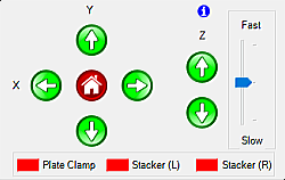
Motion Control Pad
Follow the instruction below to add a new well plate to your plate library.
In the Tools menu, click Plate Type Editor.
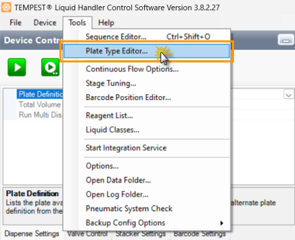
Plate Type Editor Option
Go to the File menu and select New to start the New Plate Type wizard. You can also use the Ctrl+N function on your keyboard.
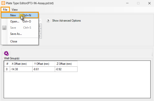
Select New to Start the New Plate Type Wizard
Put the desired plate on the TEMPEST plate holder.
Provide the following information in the New Plate Type wizard:
Choose from the following options to define the Number of Wells:
Select a common plate type from the Number of Wells selection. TEMPEST provides you with 24, 96, 192, 384, 1536, and 3456 well-plate numbers defaults.
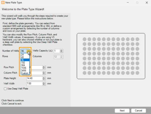
Selecting the Number of Wells
If you want to specify your own layout, select Custom from the Number of Wells option. Then, define the number of Rows and Columns from the provided fields.
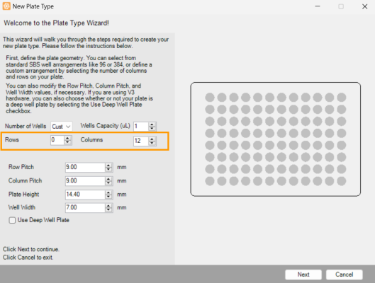
Define the Number of Wells from the Rows and Columns Fields
Input the Wells Capacity (µL) values based on the labware data sheet.
After defining the Number of Wells and Wells Capacity (µL), TEMPEST will automatically populate the row pitch, column pitch, plate height, and well width based on ANSI/SLAS standard values. Please check these values and necessarily modify them to match your microplate data sheet. Proceed to step 5 if you do not need to make any adjustments or follow the steps below to modify the values.
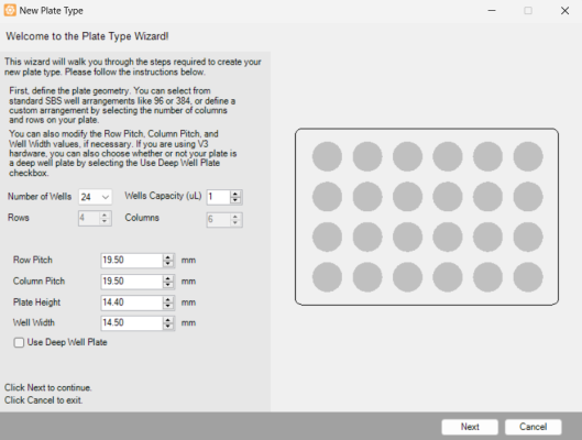
The Plate Type Editor Wizard
Input the Row Pitch (in millimeters) to define the distance between one well’s center point to another well’s center point in an adjacent row.
Input the Column Pitch (in millimeters) to define the distance between one well’s center point to another well’s center point in an adjacent column.
Input the Plate Height (in millimeters) to define the height of your plate. The plate height value may vary from plate type to plate type. The default value for a standard plate is 14.40 mm, while the default deep well plate height is 44.0 mm.
Note: You can switch between these two defaults by selecting or deselecting the Use Deep Well Plate option. If you don’t have the plate height information available for your plate, you can overestimate the value and then adjust the dispense position later on.
Input the Well Width (in millimeters).
When you’re done, click Next to define the A1 position. This position will be used by the software as an origin point to calculate the well map during the subsequent steps.
By using the Motion Control Pad, precisely move the Top-Left nozzle into position above the A1 well (or equivalent) of your microplate. Visually inspect the nozzle to verify that it is accurately positioned over the center of the A1 well on the plate. Adjust the position if necessary.
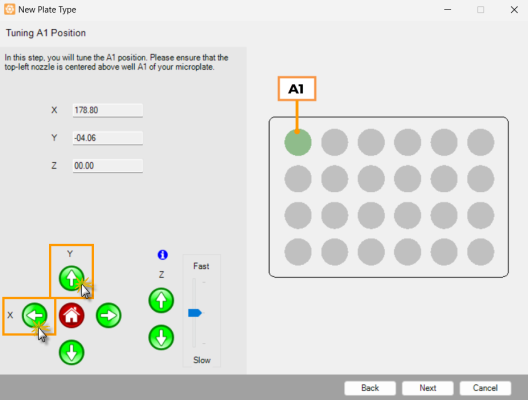
Tuning the A1 Position
When you have finished, click Next to inspect the generated plate position.
Check the nozzle positions for each well group to ensure that they are aligned with the wells. If they are not, you can modify the X, Y, and Z values using the Motion Control Pad. The nozzles are represented in the wizard by either yellow, orange, or gray dots, as explained below:
For a 24-well plate, the dispense position must be set so that each well can be dispensed by at least one nozzle, and the nozzles should be positioned approximately 1-2 mm above the plate. In the first image of the example below, the nozzle positions for well D4 are not completely inside the well. The second image shows the nozzle positions after being adjusted, so that all of the wells can be dispensed by at least one nozzle.
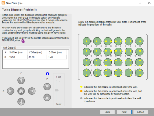
The Nozzle Positions Before Adjustments
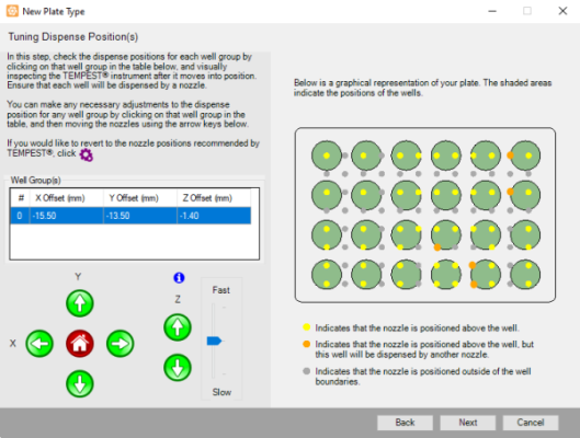
The Nozzle Positions After Adjustments
For a 96-well plate, the generated nozzle positions should be aligned with the wells, approximately 1-2 mm above the plate.
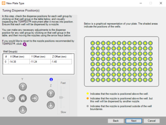
Tuning the 96-well Plate Dispense Positions
For a 192, 384, 1536, or 3456-well plate, each of the generated nozzle positions should align with a subset of the wells, approximately 1-2 mm above the plate.
For example, Well Group 0 might include wells A1, A3, A5, A7, C1, C3, C5, C7, etc., whereas Well Group 1 includes wells A2, A4, A6, A8, C2, C4, C6, C8, and so on. TEMPEST ensures that each well on a plate is included in one of the well groups.
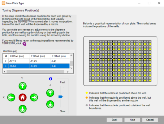
A 384-well Plate Graphical Representation
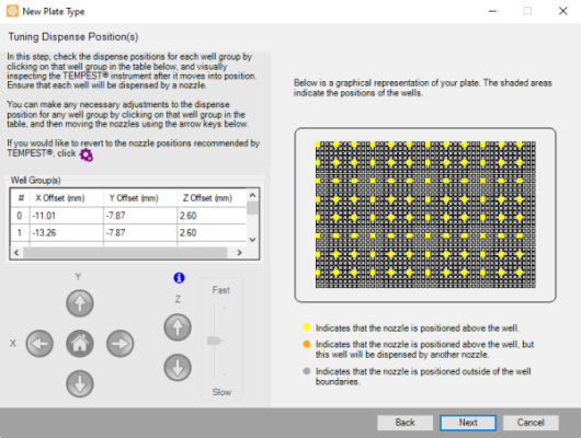
A 1536-well Plate Graphical Representation
If you are not satisfied with the results, click the Auto Generate button ![]() to revert to the positions recommended by TEMPEST, and then adjust the positions as needed.
to revert to the positions recommended by TEMPEST, and then adjust the positions as needed.
Click Next to proceed to the next step.
Type the plate name and then click Finish to save your plate definition.
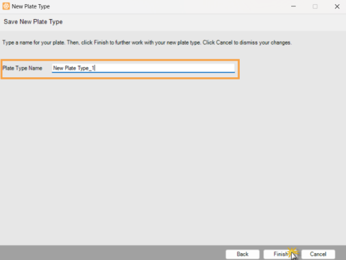
Type a New Plate Type Name
You have successfully added a new plate type in the Plate Type Editor. To learn how to modify the plate settings, go to the Modifying an Existing Plate Type section below.
Occasionally, you might want to modify the settings of an existing plate type in the TEMPEST plate type library. Follow these steps below to make adjustments to your existing plate definitions.
Open the Plate Type Editor window from the Tools menu.
Go to the File menu, and click Open. You can also use the Ctrl+O function on your keybaord.
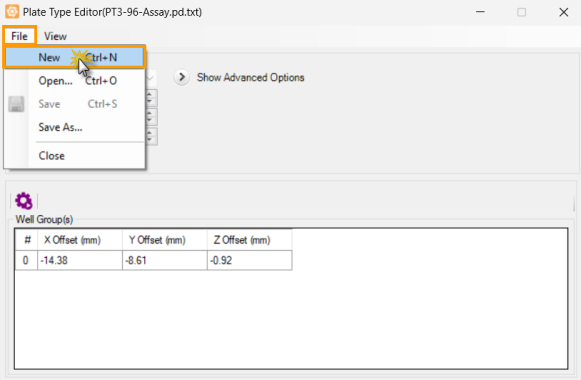
Select Open to Open the Plate Library Wizard
In the Plate Library window, open the selected plate type. The details of the plate you chose are displayed under the plate image.
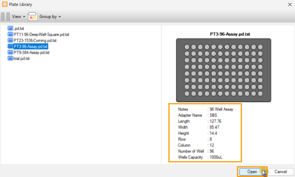
Selected Plate Type in The Plate Library Window
Click the Show Advanced Options button to expand the plate settings. Then, modify the necessary parameters as follow:
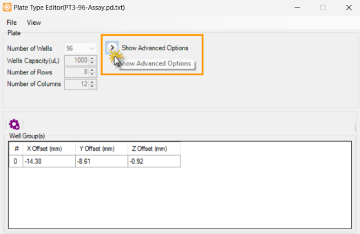
Click the Show Advanced Options to Expand the Settings
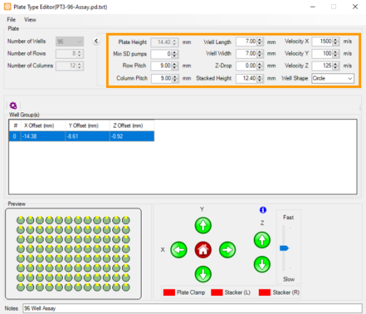
Plate Type Editor Parameters
Type the height of the plate in millimeters in the Plate Height option.
Type the minimum number of small diaphragm pumps to be used in the Min SD Pumps option. This setting forces the TEMPEST to use the Small Diaphragm for the specified number of drops prior to using the Large Diaphragm. For example, when you use a High Volume chip to dispense 10 µL and your Min SD Pumps number is 5, TEMPEST will dispense five 1 µL drops using the Small Diaphragm followed by one 5 µL drop using the Large Diaphragm. For more information, see TEMPEST Chip Specifications.
Note: This feature is useful for preventing splashing that can occur when dispensing into round or conical bottomed plates. If splashing occurs when dispensing into your plate, setting this number to 5 or higher will greatly reduce or eliminate the splashing.
Row Pitch determines the distance between one well’s center point to another well’s center point in an adjacent row, in millimeters.
Column Pitch determines the distance between one well’s center point to another well’s center point in an adjacent column, in millimeters.
Well Length determines the length of the well in millimeters.
Well Width determines the width of the well in millimeters.
Z-Drop determines the distance that the plate stage is lowered during movement, in millimeters. This feature is useful to lower the plate away from the chip nozzles when the plate definition has been set very close to the nozzles to minimize splashing. The default value is zero.
Stacked Height determines the height of the plate (in millimeters), after it is stacked with other plates when you use the plate stackers. The height can be calculated by measuring the height of two identical plates stacked and subtracting the height of a single plate (Plate Height). If you change the Plate Height value, the stacked height value will be updated automatically.
Velocity X determines the movement speed along the X axis. The default speed is 1500 m/s. Please note that while this default speed is safe for plates with 96 wells and more, you may find it necessary to decrease the velocity for plates with larger, more shallow wells to avoid sloshing during movement.
Velocity Y determines the movement speed along the Y axis. The default speed is 100 m/s.
Velocity Z determines the movement speed along the Z axis. The default speed is 125 m/s.
Well Shape determines the shape of the well, whether it is circular or rectangular.
Put your plate on the TEMPEST plate holder.
OPTIONAL: By using the Motion Control Pad, modify the X, Y, and Z values for each row to position the wells under the nozzles. The nozzles should be positioned over the center of the wells, approximately 1-2 mm above the plate. If you are not satisfied with the results, click the Auto Generate button ![]() to revert to the positions recommended by TEMPEST, and then adjust the positions as needed.
to revert to the positions recommended by TEMPEST, and then adjust the positions as needed.
OPTIONAL: Go to the View menu and select Advanced to modify the dispense positions manually or automatically.
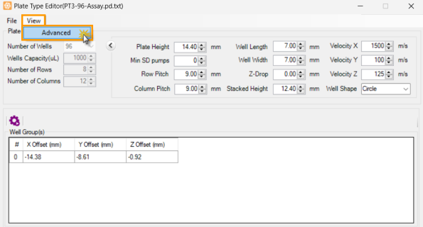
Click Advanced under the View Tab
The Advanced view allows you to change the well group update mode and change the nozzle/well assignment.
Important: The nozzle/well assignment option is for advanced users only and is not covered in this document. Please contact support@formulatrix.com if you require assistance.
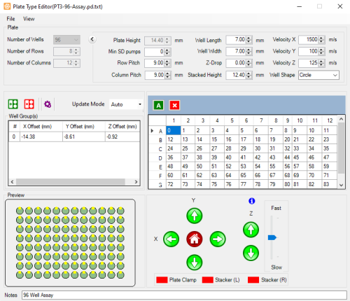
Advanced View in the Plate Type Editor
The default update mode is Auto. It’s behavior is identical to non-advanced mode of the plate type editor. It applies any changes made to a single well group’s origin coordinates across all other well groups.
For plates with multiple well groups and non-standard layouts you might find it necessary to adjust the well group coordinates individually. Follow the instructions below to manually adjust the coordinates:
Select Manual in the update mode list next to the Auto Generate button ![]() .
.
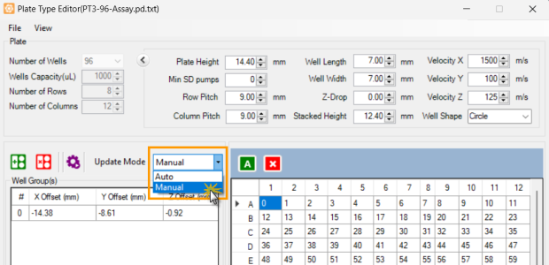
Select Manual in the Update Mode List
Select the well group you would like to adjust. The TEMPEST will move to the currently specified coordinates.
Use the Motion Control Pad or the keyboard keys to fine-tune the plate position under the nozzles. The nozzles should be positioned over the center of the wells, approximately 1 mm above the plate. Please note that in manual update mode each well group has to be adjusted individually, and you will need to repeat the process for all of the well groups you wish to modify. If you are not satisfied with the results, click the Auto Generate button ![]() to revert to the positions recommended by TEMPEST, and then adjust the positions as needed.
to revert to the positions recommended by TEMPEST, and then adjust the positions as needed.
When you have finished, proceed to step 8.
Click Save under the File menu to save your changes. You can also use the Ctrl+S function on your keyboard.
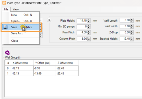
Save the Modified Plate Type Definition
 | |
| TOW-V38R123
|