Prerequisites
- You have prepared a reagent for the test drop.
- You have attached the tube input adapter on the chip. Ignore this prerequisite if you are using a pipette tip.
- You have attached a chip to the MANTIS hand.
Note: You can use the keyboard keys to control the MANTIS arms motion when adding or modifying plate types.
W: The key moves the MANTIS arms backward along the Y Axis.
S: The key moves the MANTIS arms forward along the Y Axis.
A: The key moves the MANTIS arms left along the X Axis.
D: The key moves the MANTIS arms right along the X Axis.
R: The key moves the MANTIS arms upward along the Z Axis.
F: The key moves the MANTIS arms downward along the Z Axis.
To add a new microplate to your plate library:
-
On the Tools menu, click Plate Type Editor.
-
Go to the File menu, select New, and then select Rectangular Plate. This will start the new plate type wizard.
Note: To add a circular plate, see Adding Circular Plates to the Plate Type Library.
-
On the wizard, select the Number of Wells from the list of typical SBS well numbers or if you want to add a custom plate, select Custom and set the number of rows and columns.
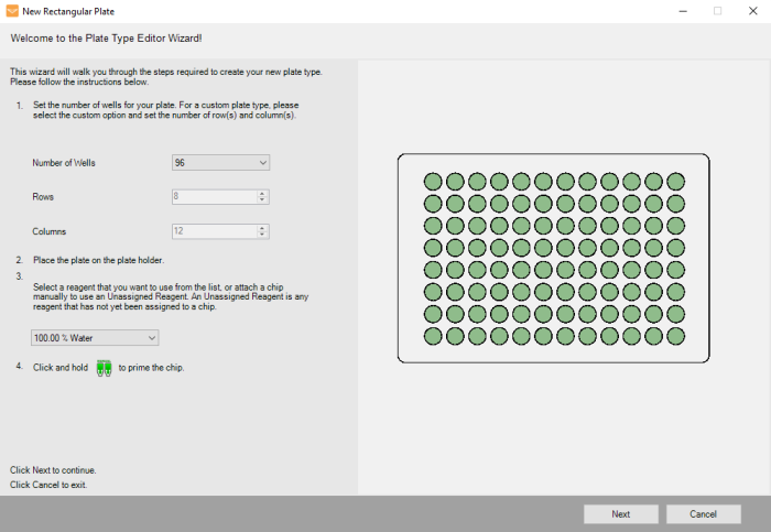
Plate Type Editor Wizard
-
Place your new plate on the plate holder.
-
MANTIS needs to pick up a chip in order to proceed with the plate tuning procedure. You can use the reagent assigned to that chip can to dispense test drops while tuning your plate. Choose one of the following options:
-
Select a reagent from the Select Reagent list to use that chip for the plate tuning procedure. MANTIS will automatically attach the assigned chip to the MANTIS hand.
-
Select Unassigned Reagent if you want to use a reagent that has not been assigned to a particular chip. When you use an unassigned reagent, you must manually attach the desired chip to the MANTIS hand. Make sure you have prepared a bottle or pipette tip containing the desired reagent if you want to dispense test drops during the procedure.
Note: When you select the Unassigned Reagent, a warning icon
 will appear in the A1 Offset tab under Dispense Location settings to remind you to assign the chip manually.
-
-
Click and hold the prime button
 to prime the chip and then click Next.
 -
Set the top-left well position by clicking the arrows, or use keyboard keys to control the MANTIS hand to aim the nozzle tip at the top-left well. Then click the Dispense button
 to dispense the test drop. If you are satisfied with the position, click Next.
Note: For best results leave approximately 2 mm clearance between the top of the plate and the chip nozzle.
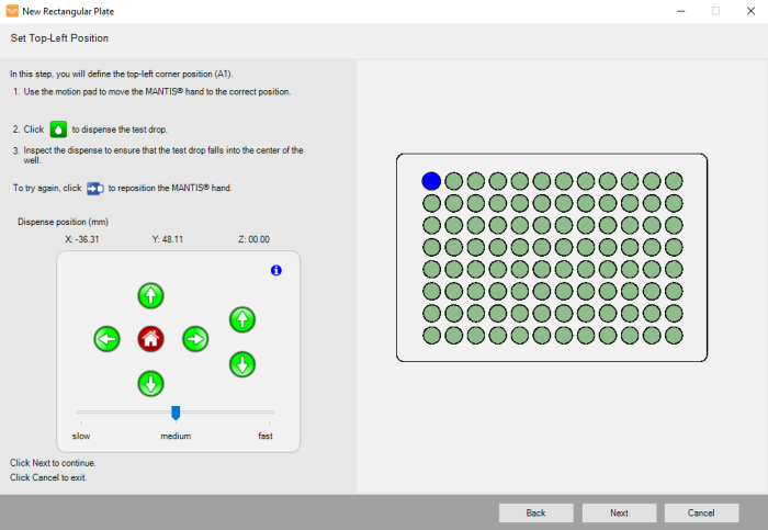
Top-Left Position Settings
-
Set the bottom-left well position by clicking the arrows or use keyboard keys to control the MANTIS hand to aim the nozzle tip at the bottom-left well. Then click the Dispense button
 to dispense the test drop. If you are satisfied with the position, click Next.
 -
Set the top-right well position by clicking the arrows or use the keyboard keys to control the MANTIS hand to aim the nozzle tip at the top-right well. Then click the Dispense
 button to dispense the test drop. If you are satisfied with the position, click Next.
 -
Set the bottom-right well position by clicking the arrows or use the keyboard keys to control the MANTIS hand to aim the nozzle tip at the bottom-right well. Then click the Dispense
 button to dispense the test drop. If you are satisfied with the position, click Next.
 -
Type the name of your plate and click Finish to complete the wizard and proceed to the Plate type Editor for fine-tuning. Click Cancel to dismiss your changes.
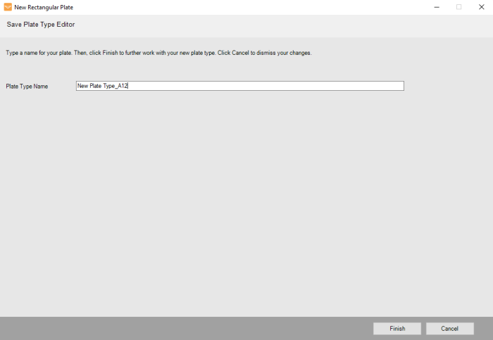
New Plate Name
-
From the Generated Well Map tab, check the dispense locations by following the steps below:
-
Click on any text locations links.
-
Search the well location by entering the well’s position on the Search Well Location field. Press Enter on your keyboard.
The MANTIS will then move its arms to the selected location (corner wells are the most indicative of any errors).
-
-
OPTIONAL: If the dispense location needs adjustment, click the Edit Rows button
 to enable the X, Y, and Z coordinates editing on the selected wells and follow the instructions below.
-
Set the selected well position by choosing the following options.
-
Change the coordinate values in the provided X, Y, and Z fields under the table.
-
Use the Motion Control Pad at the lower right of the Plate Type Editor wizard to modify the well position. Use the arrow keys to maneuver the MANTIS hand to the selected location of your plate.
Important: While adjusting the well position, view the plate from both the side and the front to ensure your center location is correct.
-
-
Repeat step a to edit other positions.
-
Click the Finish Edit Rows button
 when you have finished editing the selected well positions.
Note: Click Discard All Changes button
 to revert the well positions back to the most recently specified values and then click Yes on the dialog box to continue. If you want to change other well positions, select the wells you want to test and repeat steps c-d to modify the values.
 -
Click the Test Dispense button
 to dispense a test drop to the wells. The drop should be in the selected wells.
Generated Well Map Tab
-
-
OPTIONAL: If you find that the geometry parameters determined by the wizard require further adjustment, please follow the steps below:
-
Click the A1 Offset tab.
-
Click the Move To A1 Position button
 . The MANTIS will go to the A1 well location.
 -
Use the Motion Control Pad at the lower right of the Plate Type Editor to modify the A1 well position. Use the arrow keys to maneuver the MANTIS hand to the A1 location of your plate. View the plate from both the side and the front to ensure your center location is correct.
-
Click the Test Dispense button
 to dispense a test drop to the A1 well. The drop should be in the A1 well.
 -
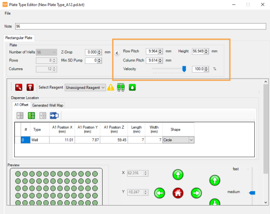
OPTIONAL: Modify the Row Pitch and Column Pitch values on the Advanced Options if the other well positions are not accurate.
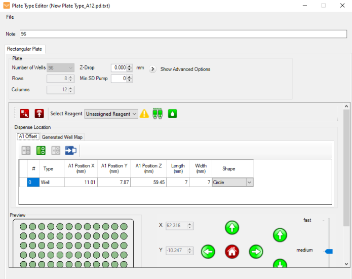
-
-
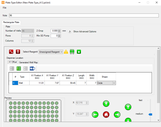
OPTIONAL: Modify the Z-Drop and Min SD Pump next to the plate settings:
-
Z-Drop determines the distance you would like MANTIS to move down into each well before dispensing (default is zero).
-
Min SD Pump determines the minimum enforced number of Small Diaphragm pumps (default is zero). This forces the MANTIS to use the Small Diaphragm for a larger portion of the dispense, if possible.
Note: This feature is useful for preventing splashing that can occur when dispensing into round or conical bottomed plates. If splashing occurs on your plate, setting this number to 5 or higher will greatly reduce or eliminate the splashing altogether.
-
-
OPTIONAL: You can modify the advanced options by clicking the Show Advanced Options menu.
-
Row Pitch determines the distance between one well center point to another in an adjacent row.
-
Column Pitch determines the distance between one well center point to another in an adjacent column.
-
Velocity limits the arm movement speed to the specified percentage of the maximum velocity. Default is 100%, which is recommended for most plate types. 80% is recommended if you find that your 1536 well plate dispenses causes the MANTIS arms to wobble.
-
Height determines the height of the plate.
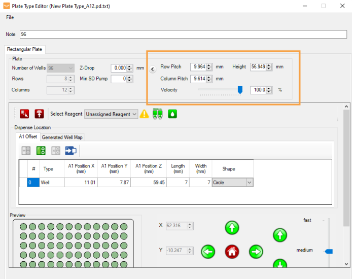
Advanced Options
-
-
OPTIONAL: If you want to add coordinates for a drop well location on the plate (useful for crystallography-type plates), follow the instructions below:
-
Go to the A1 Offset tab.
-
OPTIONAL: Click and hold the Manual Prime button
 until the chip begins dispensing drops.
 - Click the Move To A1 Position button
 . The MANTIS will go to the A1 well location.
 -
Click the Add Drop Location button
 .
. - Use the Motion Control Pad at the lower right of the Plate Type Editor to modify the drop position. View the plate from both the side and the front to ensure your center location is correct.
-
Click the Test Dispense button
 to dispense a test drop. The drop should be in the new drop location.
-
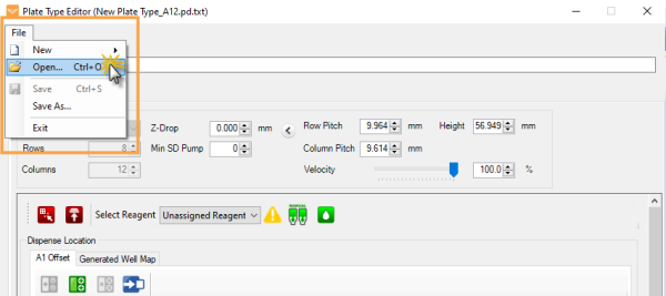
- Go to the File menu in the Plate Type Editor wizard, click Save As, type a name for your plate, and click Save.
OR
Go to the File menu in the Plate Type Editor wizard, and, click Save (Ctrl+S) to save your changes.
You have successfully added a new plate type in the Plate Type Editor. To modify the plate settings, go to the Modifying an Existing Plate Type section.
