Connect the µPULSE hardware to a power outlet using the power cable.
Find the power button located on the back of the µPULSE hardware and turn it on.
Open the chip cover.
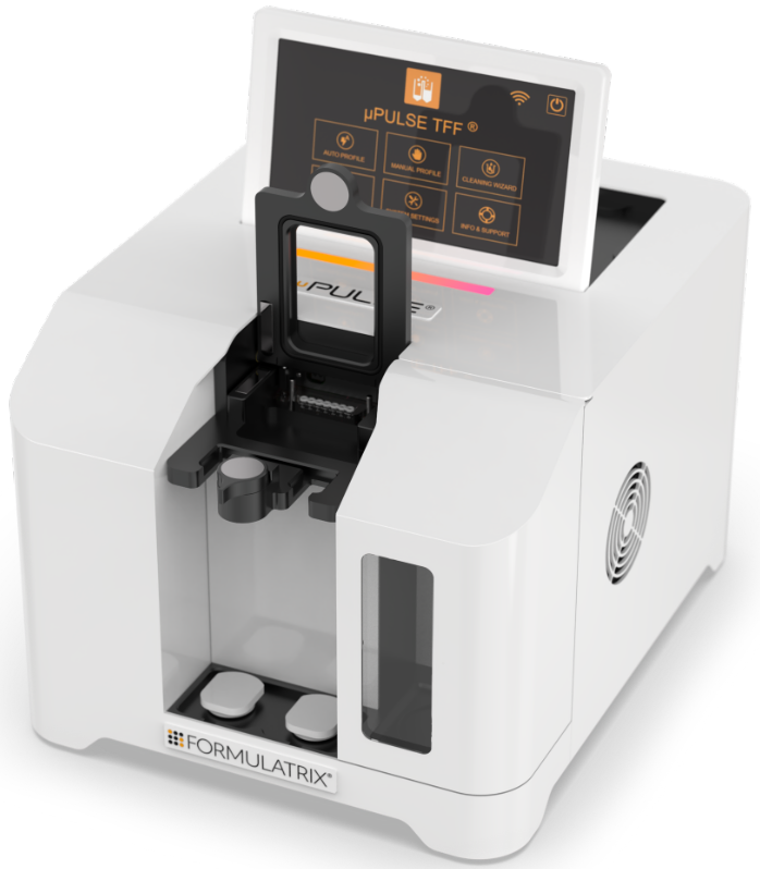
The µPULSE Instrument with the Chip Cover Opens
Open the waste door, insert the waste tank, and then insert the waste slide into the slot over the tubes.
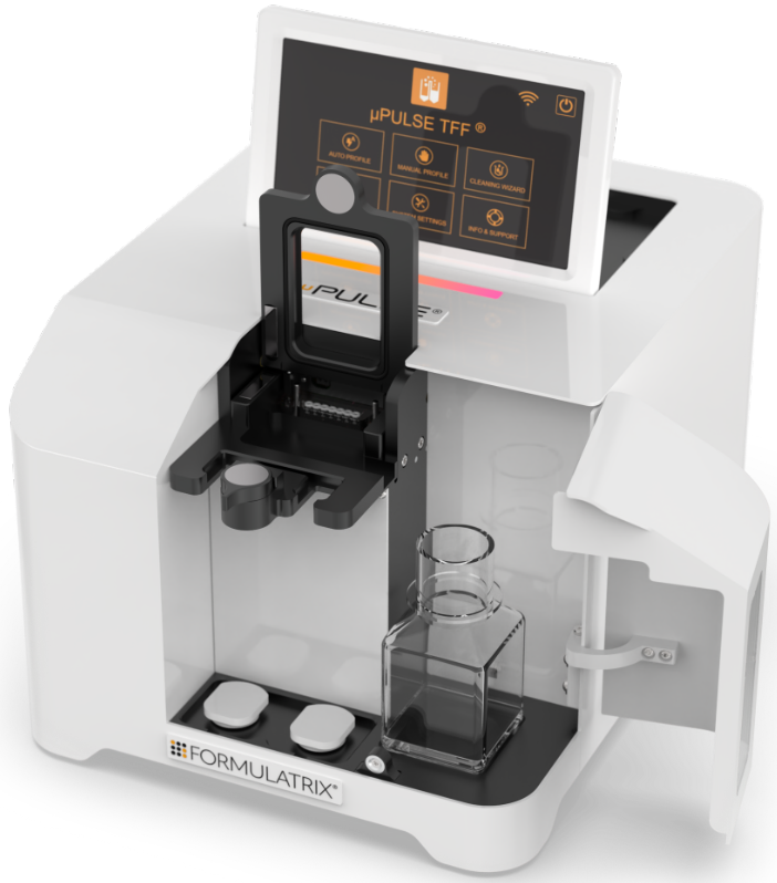
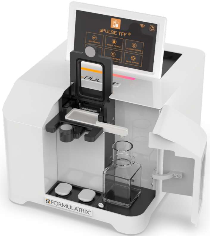
The µPULSE Hardware with the Waste Tank and Waste Slide Are Attached
Fill the sample tube with the sample or your carrier reagent. This tube should go in the left input.
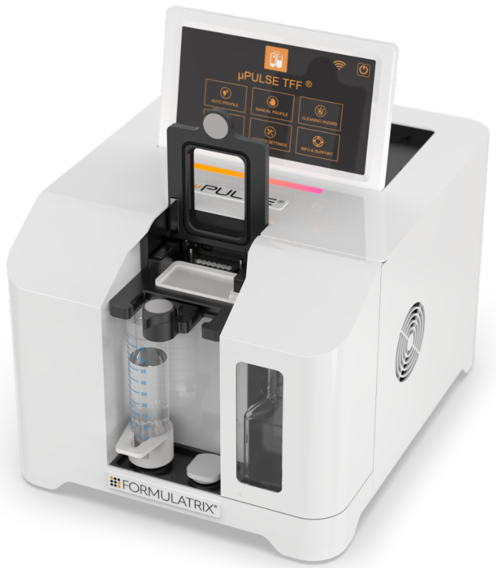
A Sample Tube Is Attached on the Left Input
Fill the buffer tube with the buffer of your choice. This tube should go in the right input.
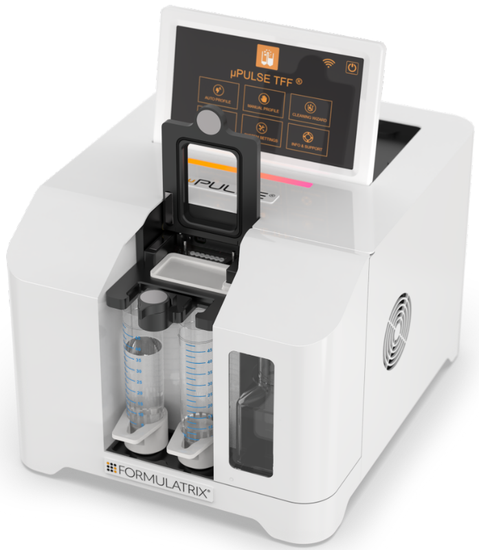
A Buffer Tube Is Attached on the Right Input
Put the tubing block into position, make sure the 1/16" tubings are inside the tubes.
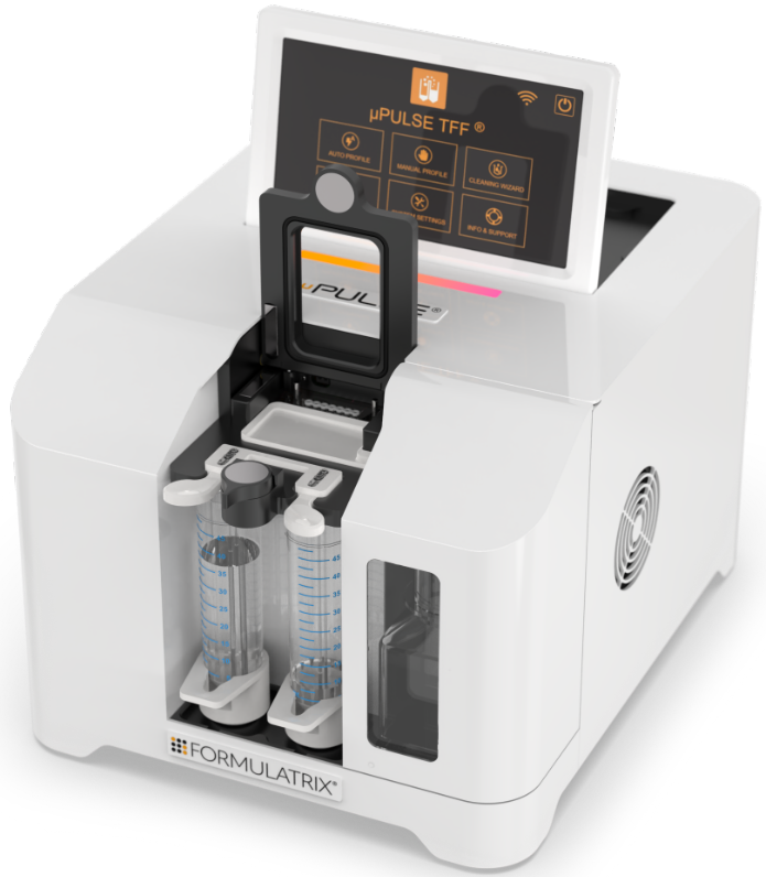
The Tubing Block Is Securely Attached to the Tubing Mount
Attach the desired chip with the diaphragm side facing the front of the instrument. µPULSE filter chips come with six membrane cutoff sizes: 5, 10, 30, 50, 100, and 300 kDa. Choose the chip that corresponds to the size of the sample you are using. Typically, you should use a cutoff size that is less than half the size of the sample or target of interest you want to concentrate.
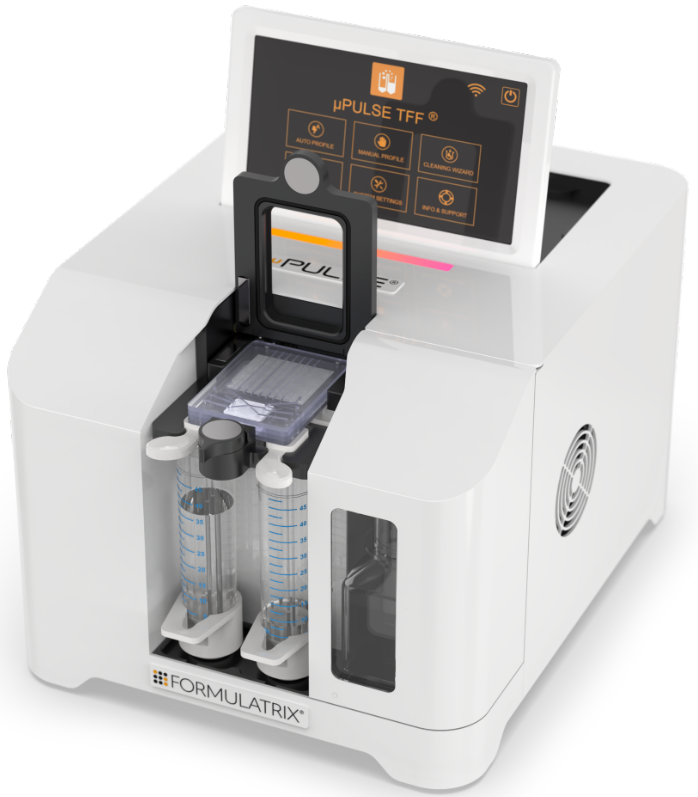
The Filter Chip Is Attached
Press down the chip cover until the latch has caught. If there is resistance, please make sure that the tubing block and filter chip are seated properly.
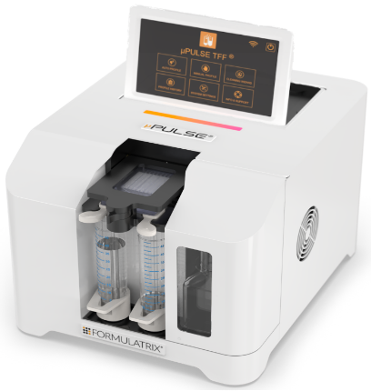
The Chip Cover and the Waste Door Are Closed
