
Before you set up the µPULSE instrument, you’ll need to understand the names of its components and where each component is located on the system.
µPULSE - Front View
![]()
New Transfer Tubing

50 mL Sample Tube and Buffer Tube

Permeate Collector
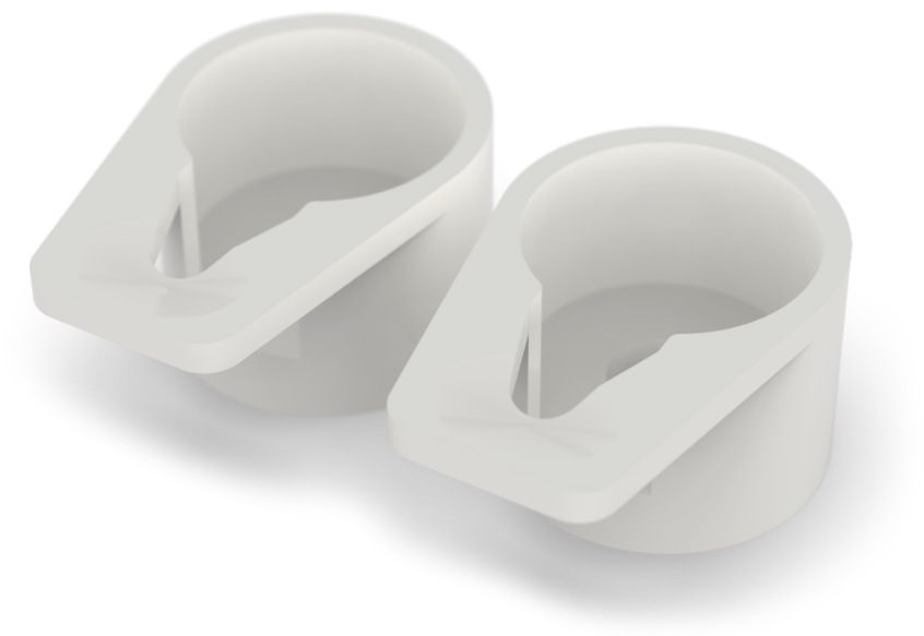
New 50 mL Tube Adapter

Tube Stands
LED Indicator
The LED indicator displays instrument status or behavior.
| Color | Description |
| White to Green | The system is running protocol. |
| Yellow (Blinking) | Paused during a protocol execution. |
| Red | An error has occurred or the system detects a failure. |
| Multicolor | The system is idle. |
Power Button
The various colors of the power button indicate the following status and behavior.
| Color | Description |
| Red (Blinking) | µPULSE is starting on or turned off. |
| Red (Solid) | µPULSE is already stabilized and successfully connected to the software. |
The touch screen controls the µPulse software.
The chip cover securely holds the chip in place.
Rotate the lever from left to right to open the chip cover.
µPULSE filter chips come with various membrane cutoff sizes: 5, 10, 30, 50, 100, and 300 kDa. See also, Chip Overview.
Note: Filter chips can be purchased from the FORMULATRIX online store at https://wcm.formulatrix.com/.
The permeate collector transfers waste liquids from the chip to the permeate bottle.
The permeate bottle door keeps the permeate bottle covered. You can easily check the bottle capacity through the window in the waste door.
The instrument accepts both 50 mL conical tubes (using the supplied tube stands) or a 125 mL bottle.
The transfer tubing connects to the chip for aspirating and returning the sample and/or buffer to the 50 mL tubes. It can be single-use or cleaned for reuse. See µPULSE Filtration Chip Manual for more information.
The left input of the µPULSE is for your sample. The right input can be used for additional sample or buffer. The system is compatible with all common varieties of 50 mL conical tubes.
The balance pad provides a repeatable place for the tube adapter to sit. It detects and calculates volume changes when the µPULSE is running profiles.

µPULSE Balance Pad
The tube adapters couple the 50 mL conical tube to the system's balance pad.

µPULSE - Back View
The Ethernet port is used to connect the µPULSE instrument to the Internet through hard-wire.
The USB port is used for updating the µPULSE software manually if an Internet connection is not available. It may also be used by support for debugging or troubleshooting purposes.
The power button  turns the µPULSE On or Off. To turn off the device, it is preferred to shut down the system by tapping the SHUTDOWN button on the Home Screen. Then, press the power button.
In the same way as a software shutdown, pressing the power button once will perform a normal shutdown.
Pressing and holding the power button for more than 5 seconds and releasing it will perform a "hard" shutdown.
The power port is where you plug in the power cable. See also, Electrical Requirements.
The filter chips come with six membrane cutoff sizes: 5, 10, 30, 50, 100, and 300 kDa.

Filter Chip Overview
Each filter chip consists of the following components:
Membrane: The membrane is what separates the sample (retentate) from its carrier reagent (permeate) which flows to the permeate bottle.
Diaphragm: The diaphragm pumps the liquid through the filter chip.
Liquid Layer: The liquid layer is the channels through which the liquid flows.
Air Layer: The air layer is the channels through which air flows to actuate the diaphragm.
| PUOWH-V24R023 |