Important
This web help is an outdated version. Visit the latest version (NT8 v4.8) here.
Deep Well Station
The deep well station in the software enables you to specify dispense, volume, and aspirate settings for deep well blocks necessary for plate copy experiments.
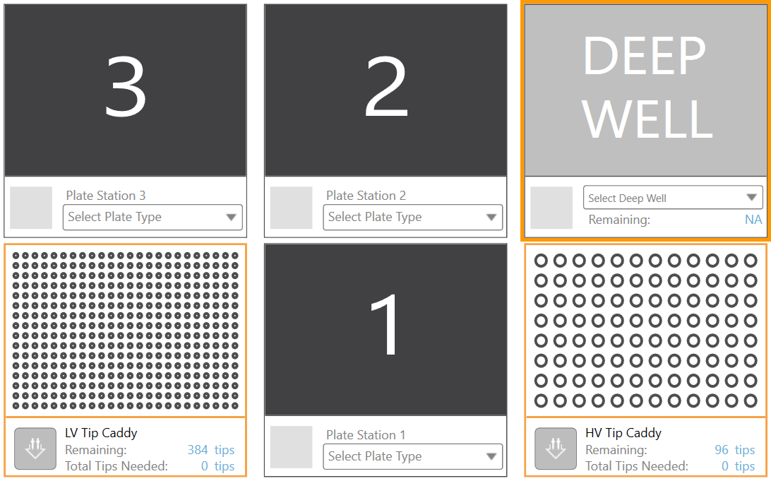
Deep Well Station
The Plate Copy head in NT8 is equipped with liquid level sensors that can automatically detect the volume inside the deep well plate. The sensors can detect even the lowest liquid level in a well. This ensures a well with different volume level from the others will not be missed by the tips during aspiration.
Aside from calculating the initial volume levels, the sensors will also collect information about the volume range levels contained inside the deep well plate. This information helps the tips to determine the heights at which they will stop prior to aspirating. By default, the sensors are always active but you can turn them off if you want to set the initial volume levels manually.
To turn off the Plate Copy tips sensors:
Go to the Tools menu and select Touch Sensors Config.
Under the Plate Copy Tips Liquid Level section, make sure you toggle off all the sensors, as shown below.
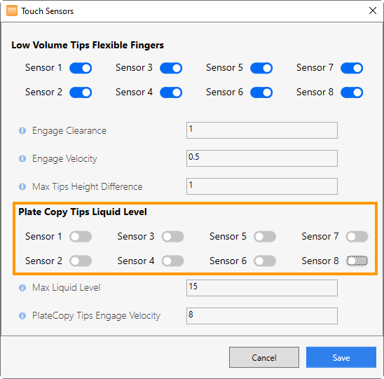
Switching Off All Sensors in the Plate Copy
Click Save to save the changes.
Setting the Initial Solution Levels Manually
If the liquid detection sensors are not active, you must manually specify the initial solution levels on the well columns before running the plate copy experiment.
To set the initial solution levels:
In the NT8 Control Software, click the down-arrow under the deep well station and select a deep well plate from the Plate Selection.
Right-click the deep well station and select Set Initial Solution Level. The Deep Well Levels Setup dialog box appears as shown below. There are 12 graphics that represent the well columns and each of them has 20 level numbers. Level #1 is located at the bottom and level #20 is at the top.
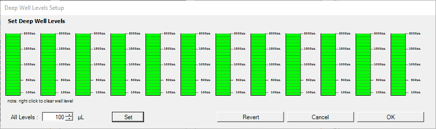
Deep Well Level Setup Dialog Box
Warning
The specified volume in the software should be the same as the actual deep well plate volume.
Set the well volume to aspirate by clicking the desired level numbers (#1 through #20) on every column/graphic as necessary or by typing a new level value in the All Levels box then clicking Set, and then clicking OK to confirm. The specified level numbers will be reflected on the Deep Well Volume Range see Setting the Solution Volume Range Level below.
OPTIONAL: Setting the Solution Volume Range Levels
To set the solution volume range level:
At this point, you must have already set the solution levels.
Right-click the deep well station and select Set Volume Range Level. The Deep Well Volume Range - Levels Setup dialog box appears as shown below.
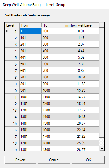
Deep Well Volume Range Dialog Box
Item
Description
Level
The deep-well level number. Level #1 is the closest level to the plate surface (located at the bottom) and level #20 is located at the top.
From
The starting point of the volume range levels on each deep-well level number.
To
The end point of the volume range levels on each deep-well level number.
mm from well base
The clearance (in millimeters) between the HV tips and the deep-well plate surface.
Double click the From and To columns in the desired Level number.
Type a new value in each column as needed.
After you have specified the solution levels and the solution volume range levels, you can then create the deep-well aspirate and dispense commands, explained below.
To create the deep well aspirate command:
Double-click the HV Tip Caddy to add the Pick Tip command to the Task List.
Click the Repeat button on the Task List to tell the NT8 that you want to repeat this task for all columns.
Click the down-arrow in the Select Plate Type field under the deep well station and select the appropriate deep well type, i.e. matching the hardware setup.
Double-click the deep well plate. The Task Details window appears.
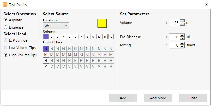
Task Details Windows for Deep Well Plates
Show me what the Task Details windows for Deep Well plates consists of
Select Operation
Provides two options: Aspirate and Dispense. Select Aspirate if you want the NT8 to aspirate and select Dispense if you want the NT8 to dispense.
Select Head
Shows the three available heads on the NT8 hardware: LCP Syringe, Low Volume Tips, and High Volume Tips. High Volume Tips is automatically selected when you have added a deep well plate to the task list.
Select Source/Select Target
Comprises of three sections:
Location
Determines the location in the plate to which the HV tips will perform the aspirate/dispense. Since Deep Well plates are used for Plate Copy and do not involve protein, you can only choose a regular well from this option.
Column
Represents the well column numbers. Select the desired well column number as needed by clicking on the corresponding number. For multiple selection, click All or hold the Shift key and click the desired well column number(s). The NT8 will perform the aspirate/dispense action to the selected columns.
Liquid Class
Provides four liquid class options: Normal (N), Medium (M), High H), and Very High (V). You have to select the appropriate reagent liquid class. If you select the Repeat command on the Task List Panel, you can apply a different liquid class to each column by selecting the corresponding button in the Liquid Class option.
Set Parameters
Comprises of three sections:
Volume
Sets the liquid volume to be aspirated or dispensed by typing a new value into the corresponding field, or clicking the up and down-arrows to increase and decrease the volume.
Pre-Dispense
For Aspirate tasks only. The Pre-Dispense field allows you to aspirate additional volume for both LV and HV tips after aspirating the targeted volume, then dispense the extra volume immediately. This is to prevent any air gap, thus ensuring accurate dispense.
Mixing
Sets the desired mixing cycles to be performed by NT8. This option determines the number of times the NT8 will mix the solution before aspirating it from the deep well block.
Add
Adds the command(s) to the Task List and closes the Task Details window.
Add More
Adds the command(s) to the Task List and waits for you to define the next task.
Close
Exits the Task Details window.
Related Topics