Mold Maker
The Mold Maker table tracks the status of mold part creation process, which starts after the approval of the part’s design in the Mold Design table. The Injection Mold Engineer (IME) division completes all information in each step of Mold Maker, including initial data input, mold part creation, and quality evaluation. The diagram below outlines the basic process.
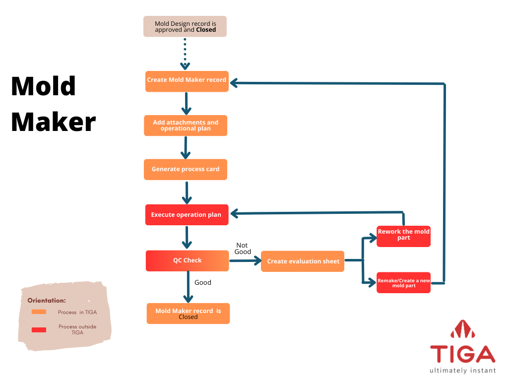
Mold Maker Flowchart
Mold Maker Request
Explains the details of the mold part, including the materials, toolpath creator, and completion date of required documents.
Attachments and Operation Plan
The attachments provide detailed procedures and images for creating the mold part, including 2D/3D drawings and NC (Numerical Control) Sheet, which is created by toolpath creator. The PPIC (Production, Planning, and Inventory Control) then provides the operation plan, which serves as a guideline for both the machine operators and mold engineers.

2D Drawing Sample of FAST Insert Cavity
Process Card
Tells the production team which machines to use to make the mold part.
QC (Quality Control) Check
If the mold part’s dimensions exceed the expected tolerance, the “QC” team will classify it as Not Good (NG). The mold engineer can use the information in the evaluation sheet to either rework the part on the CNC machines or remake the mold part.
Please check the Status column to monitor the progress of the mold design.
Status Name |
Description |
|---|---|
Draft |
Newly created record. |
Submitted |
Process card generated. |
Scheduled |
Operation plan attached |
Waiting Next Process |
The mold engineer manually updates record status to Waiting Next Process when the mold machines are busy. This step is not required if the machines are available. |
In Progress |
The mold engineer manually updates record status to In Progress when the machine is ready. |
Not Good |
Mold does not pass quality control. This status is automatically updated when Approved Status in QC Sheet table is Not Approved. |
Closed |
Status manually updated by the mold engineer if the mold part passes QC check. |
Creating a Mold Maker Request
When the design is approved, and the Mold Design table’s status is Closed, the mold engineer creates a new record in the Mold Maker table. TIGA then assigns the new record the status of Draft.

Mold Design Status in the Mold Design Table
Note
You do not have to complete all fields in the Create New Mold Maker window on the first attempt. Edit the record to update the Toolpath Schedule, Barcode Material, and Operation Plan sections.
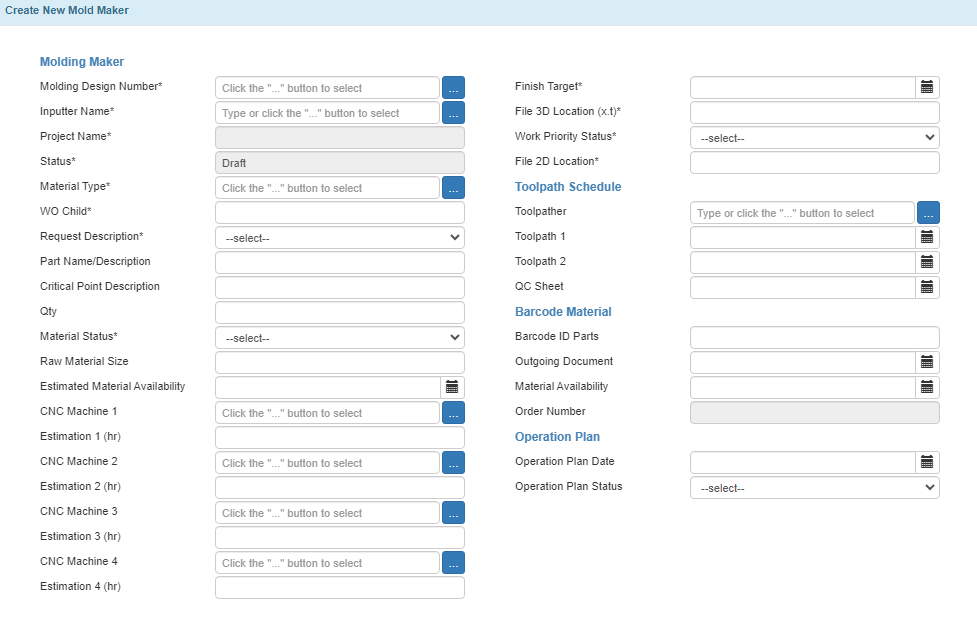
Create New Mold Maker Window
Below are the fields in the Create New Mold Maker window and their descriptions.
Molding Maker
Field Name |
Description |
|---|---|
Molding Design Number* |
The number of the approved mold design record. |
Inputter Name* |
The record’s creator. |
Project Name* |
Autofilled by TIGA based on the Molding Design Number linked. |
Status* |
The record’s status. The status of a newly created record is Draft. |
Material Type* |
Material used for creating the part. |
WO Child* |
WO Child ID created by the “Finance” team to track the cost estimation. Note The “Finance” team creates the WO Child based on the mold engineer’s request. It will be updated every half until the mold part creation finishes. |
Request Description* |
The part’s status. Tip Select New Design for a new mold part. |
Part Name/Description |
Description of the mold part. |
Critical Point Description |
Details related to dimension points requiring careful measurement. |
Qty |
Quantity of the mold part. |
Material Status* |
The status of the materials needed to create the mold part. |
Raw Material Size |
The dimension of the raw material. |
Estimated Material Availability |
The estimated date of material availability. |
CNC Machine 1 |
The first machine used to create the mold part. |
Estimation 1 (hr) |
The estimated time in hours to process the mold part in the first machine. |
CNC Machine 2 |
The second machine used to continue the mold part creation (if any). |
Estimation 2 (hr) |
The estimated time in hours to process the mold part in the second machine. |
CNC Machine 3 |
The third machine used to continue the mold part creation (if any). |
Estimation 3 (hr) |
The estimated time in hours to process the mold part in the third machine. |
CNC Machine 4 |
The fourth machine used to continue the mold part creation (if any). |
Estimation 4 (hr) |
The estimated time in hours to process the mold part in the fourth machine. |
Finish Target* |
The estimated finish date of the mold part creation process. |
File 3D Location (x.t)* |
The link to the forindosource server where the 3D file is located. |
Work Priority Status* |
Mold maker urgency (Low, Medium, Urgent, or Top Urgent). |
File 2D Location* |
The link to the forindosource server where the 2D file is located. |
Toolpath Schedule
Field Name |
Description |
|---|---|
Toolpather |
The mold engineer who creates the toolpath. Note Toolpath is a program to translate the 3D model to instructions used in CNC machines. |
Toolpath 1 |
Date of CNC program creation. Tip If the program is split, complete the Toolpath 2 field. |
Toolpath 2 |
Date of CNC program creation. Important Leave this field blank if Toolpath 1 covers all CNC programs. |
QC Sheet |
Quality control check date. |
Barcode Material
Field Name |
Description |
|---|---|
Barcode ID Parts |
Barcode ID prepared for the mold part. |
Outgoing Document |
Process card, 2D/3D drawing, and QC sheet documents’ release date. Note If the documents are not released at the same time, use the process card’s release date. |
Material Availability |
The expected date of material readiness. |
Order Number |
Project order number (auto-filled by TIGA) |
Operation Plan
Field Name |
Description |
|---|---|
Operation Plan Date |
Date of finished operation plan. |
Operation Plan Status |
The status of the operation plan, Approved or Not Approved. |
Creating a Process Card
To create a process card:
Expand the Process Card table in Mold Maker/Related Tables.
Note
TIGA will fetch most of the data from the Mold Maker record. Please complete the 2D Date, Tools Date, and QC Sheet Date.
Add a new record to the Process Card Line Item in the Process Card/Related Tables to specify the machines used in the mold part creation process.
Use the Download Process Card action to generate the card.

Process Card
Post Condition
TIGA automatically creates records in the Process Card and Process Card Line Items tables. The number of machines used to create the mold determines the number of records created in the Process Card Line Items table.

Create New Process Card Window
Below are the fields in the Process Card window and their descriptions.
Process Card/FRM-11-001-0051
Field Name |
Description |
|---|---|
2D Date |
2D attachment submission date. |
Tools Date |
Manufacturing tool availability date. |
QC Sheet Date |
QC Sheet submission date. |
Process Card Line Item
Field Name |
Description |
|---|---|
CNC Machine |
Machine used for creating mold parts. |
Process Estimation |
Time estimation of mold part creation process. |
Actual Process |
Actual time of mold part creation process. |
Note |
Additional information. |
Tip
Edit the record to manually update the status to Waiting Next Process if the next machine needed for the process is occupied.
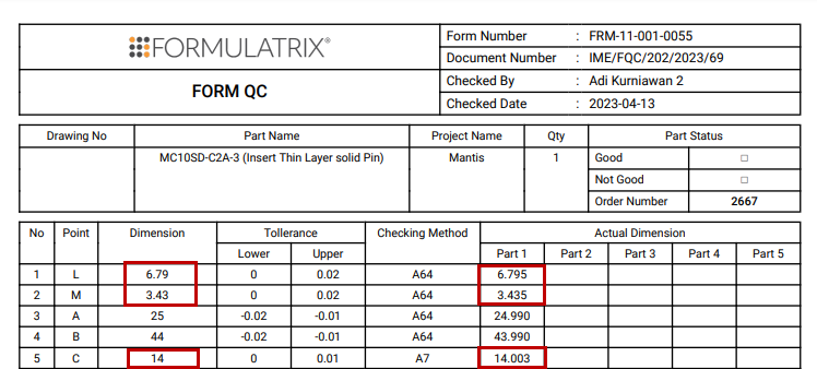
Creating a QC Sheet Report
The QC Sheet report lists the measurement of mold part dimensions. The mold engineers use the information to compare the actual and expected dimensions. The “Administrator” group will update the Mold Maker record to Closed if no dimension exceeds the tolerance.
QC Sheet
To create a QC Sheet report:
Expand the QC Sheet table in the Mold Maker/Related Tables.
Complete the QC Sheet Line Items in the QC Sheet/Related Tables to give detailed information about quality control.
Use the Download QC Sheet Report action to generate the report and get approvals from the PPIC and the IME manager.
Note
The Operation Plan, Process Card, and QC Sheet Report are required to complete the manufacturing process.
Post Condition
TIGA automatically creates records in the QC Sheet and QC Sheet Line Items tables.
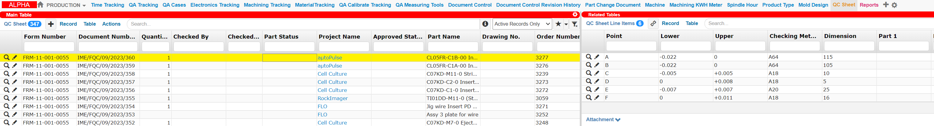
QC Sheet and Its Line Items
Below are the fields in the Create New QC Sheet window and their descriptions.
QC Sheet
Field Name |
Description |
|---|---|
Form Number |
QA document’s number. |
Document Number |
Sequential document number generated by TIGA. |
Checked By |
Checker’s name. |
Checked Date |
Quality check date. |
Drawing No. |
2D drawing number. |
Part Name |
Requested mold part name filled by the requester. |
Project Name |
Name of the product/project. |
Quantity |
Total mold part created. |
Part Status |
Mold quality based on the 2D drawing estimation. Note The validator will complete this field. |
Order Number |
Project order number (autofilled by the system). |
Validator |
The shift leader or PPIC who verifies the record. |
Approver |
The IME manager who approves the QC sheet. |
Approved Status |
Mold status based on its tolerance. Note The tolerance is indicated in the 2D Mold drawing. |
QC Sheet Line Item
Field Name |
Description |
|---|---|
Point |
The letter used to indicate a part in the 2D drawing. |
Dimension |
The targeted measurement of the Point. |
Tolerance
Field Name |
Description |
|---|---|
Lower |
Lower limit tolerance. |
Upper |
Upper limit tolerance. |
Checking Method |
Technique used for checking. |
Actual Dimension
Field Name |
Description |
|---|---|
Part 1 |
Dimension measurement result for the first part. Note If only one mold part exists, leave the other fields empty. |
Part 2 |
Dimension measurement result for the second part. |
Part 3 |
Dimension measurement result for the third part. |
Part 4 |
Dimension measurement result for the fourth part. |
Part 5 |
Dimension measurement result for the fifth part. |
Creating an Evaluation Sheet
An evaluation sheet presents detailed information on points that exceed the part’s dimension tolerance. The mold engineer must create an evaluation sheet if the Approved Status in the QC card is Not Approved.

Evaluation Sheet
To create an evaluation sheet:
Expand the Evaluation Sheet table in the Mold Maker/Related Tables.
Complete the Evaluation Sheet Line Items in the Evaluation Sheet/Related Tables to give detailed information about the mold part’s evaluation.
Note
You can use the Evaluation Sheet action to generate the sheet.
Post Condition
TIGA automatically creates records in the Evaluation Sheet and Evaluation Line Items tables.

Evaluation Sheet and Its Line Items
Below are the fields in the Create Evaluation Sheet window and their descriptions.
Field Name |
Description |
|---|---|
Form Number |
Call number of the form. |
Document Number |
Call ID created by the system. |
Fatality Rate |
Rate and cause of the Not Good mold part in the mold. Note
|
CNC Machine |
CNC machine used to create the mold part. |
Part Name |
Requested mold part’s name. |
Part Status |
Mold part status Not Good means that the mold engineer needs to remake the mold, while Remachining means that the part can be reworked. |
Project/PIC |
Product’s name. |
Date & Time |
Date when the Not Good mold part is found. |
Operators |
CNC machine operator. |
Leader Name |
The shop leader of the mold part creation. |
PIC |
Mold maker record creator. |
PPIC |
The engineer who plans the mold part creation. |
Division Manager |
IME manager. |
Evaluation Sheet Line Item
Field Name |
Description |
|---|---|
Issue |
Description of the evaluation. |
Root Cause |
The cause of the issue. |
Chronology |
Chronological explanation of the issue. |
Solution |
Possible solution for the issue. |