Labware Manager
Important
The Labware Manager feature is only available to Administrator users. These settings control the instrument’s physical movement, and incorrect values may cause crashes. Adjustment is recommended only if instructed by FORMULATRIX Support.
The Labware Manager is a tool used to calibrate labware types to ensure proper alignment and handling with racks on the deck and positioning at the stations. aµtoPULSE supports default labware types: 1.5mL Microtube 3x4, 15mL Conical Tube 4x6, 50mL Conical Tube 2x3, and Chip Caddy.
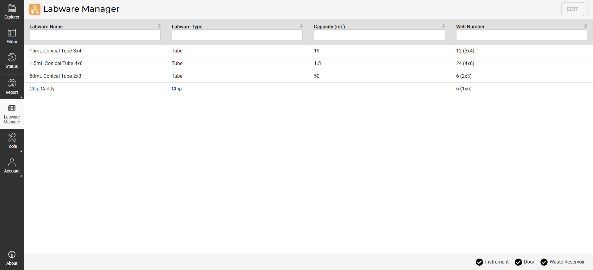
Labware Manager Page
Labware Manager is divided into two tabs:
Deck: Provides labware parameters and manual controls to calibrate labware on the deck.
Station: Provides manual controls to calibrate labware at the station.
Understanding the Labware Manager Settings
Deck Tab
Deck Tab
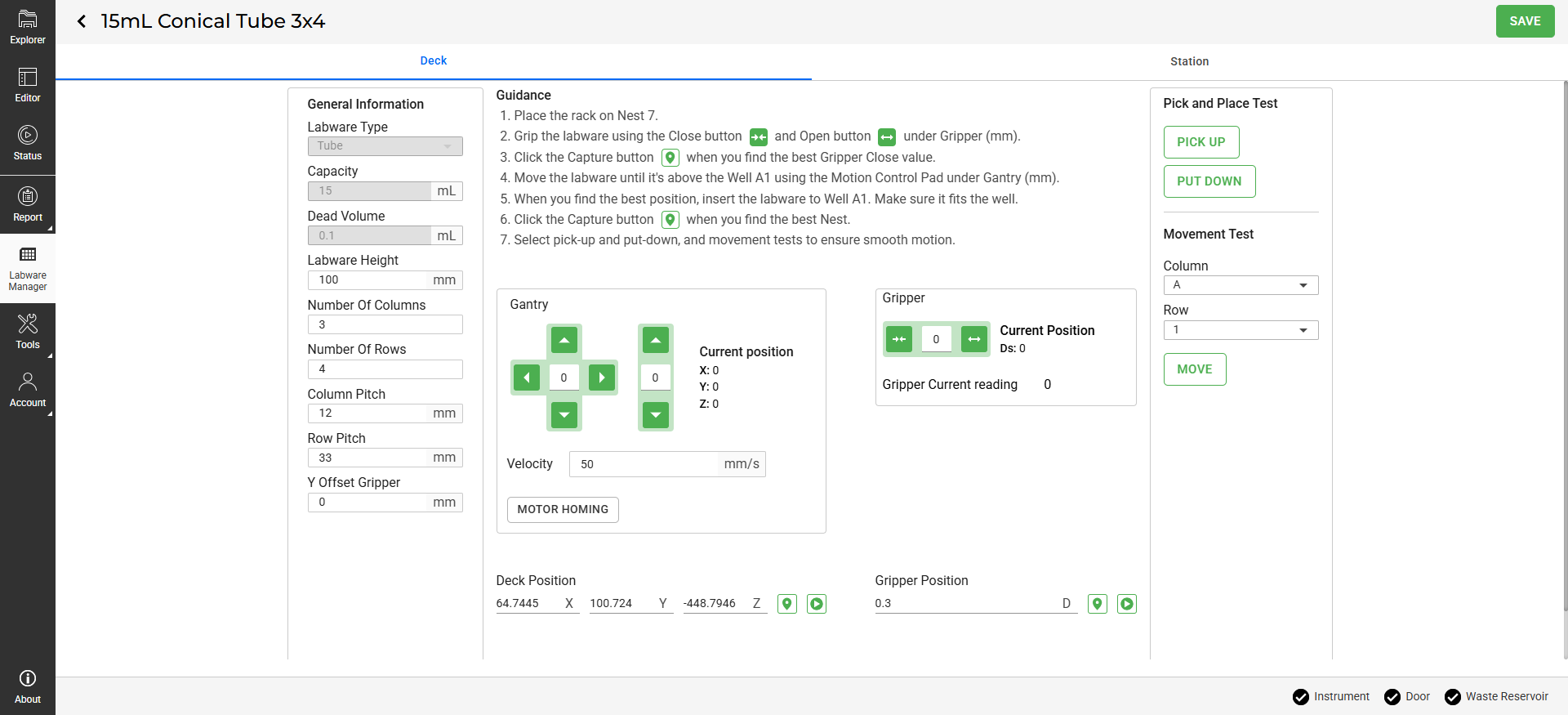
The Deck tab includes the following parameters:
Note
Parameters such as Labware Type, Capacity, and Dead Volume are predefined and cannot be modified.
Parameter/Setting |
Description |
|---|---|
General Information |
Defines labware specifications:
|
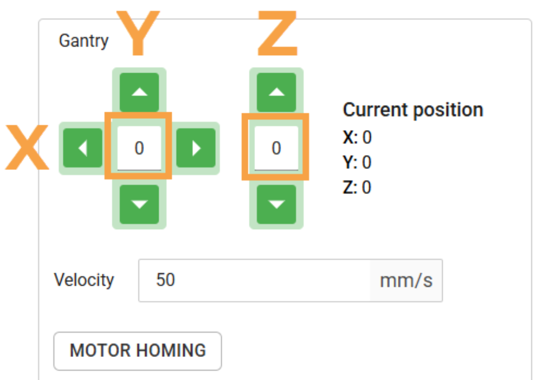
Gantry |
Use the control buttons to maneuver the gantry to the selected location on the deck. Set the step value (in mm) you want the gantry to move along the X, Y, and Z axis.
|
Deck Position |
The target gantry coordinates on the deck. Use Get Value |
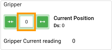
Gripper |
Use the control buttons to OPEN
|
Gripper Position |
The target gripper position. Use Get Value |
Pick and Place Test |
Use this panel to test the gantry and gripper movement on a specific rack well by clicking PICK UP |
Movement Test |
Use this panel to test the gantry movement between rack wells. Select the well position (COLUMN and ROW), then click MOVE |


Station tab
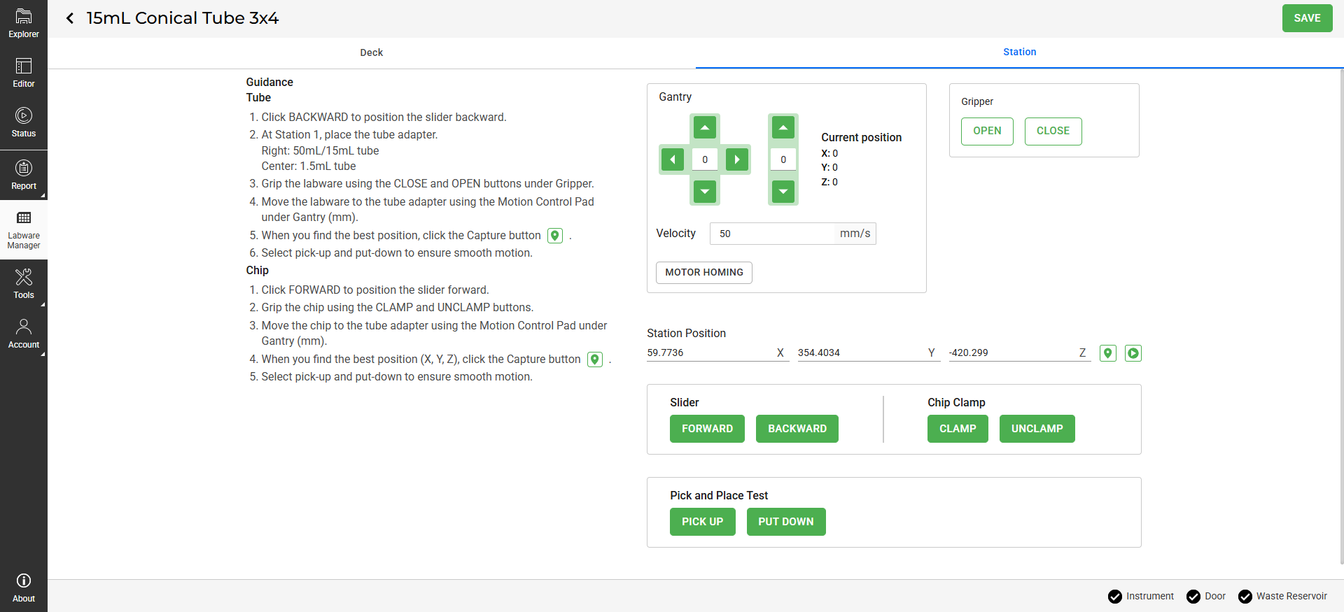
Station Tab
The Station tab includes the following parameters:
Setting |
Description |
|---|---|
Gantry |
Use the control buttons to maneuver the gantry to the selected location on the station. Set the step value (in mm) you want the gantry to move along the X, Y, and Z axis.
|
Gripper |
Use the control buttons to OPEN |
Station Position |
The target gantry coordinates on the station. Use Get Value |
Slider |
Moves the slider in the station FORWARD |
Chip Clamp |
Secure the chip in the station using CLAMP |
Pick and Place Test |
Use this panel to test the gantry and gripper movement on a station by clicking PICK UP |


Calibrating Labware
Prerequisites:
Make sure the deck and station are clear.
You have prepared the required labware type or chip.
No protocols are running.
Note
Calibration is only performed on Nest 7 and Station 1. On-screen instructions are available for your guidance.
To calibrate labware:
In the Navigation Bar, click Labware Manager.
Select a labware type or chip caddy to calibrate, then click EDIT.
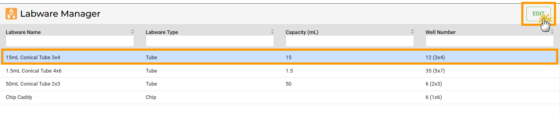
Select a Labware and Click EDIT
OPTIONAL: Click the labware name at the top left to rename it, then click on an empty space to save the new name.
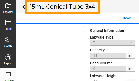
Rename a Labware
Under the Deck tab:
a. OPTIONAL: Specify the General Information according to your physical labware.
Tip
When measuring the Y Offset Gripper using the Gantry and Gripper, move slowly and in small steps to avoid hitting labware or instrument parts.
b. Follow the on-screen instructions to calibrate the tube or chip on Nest 7.
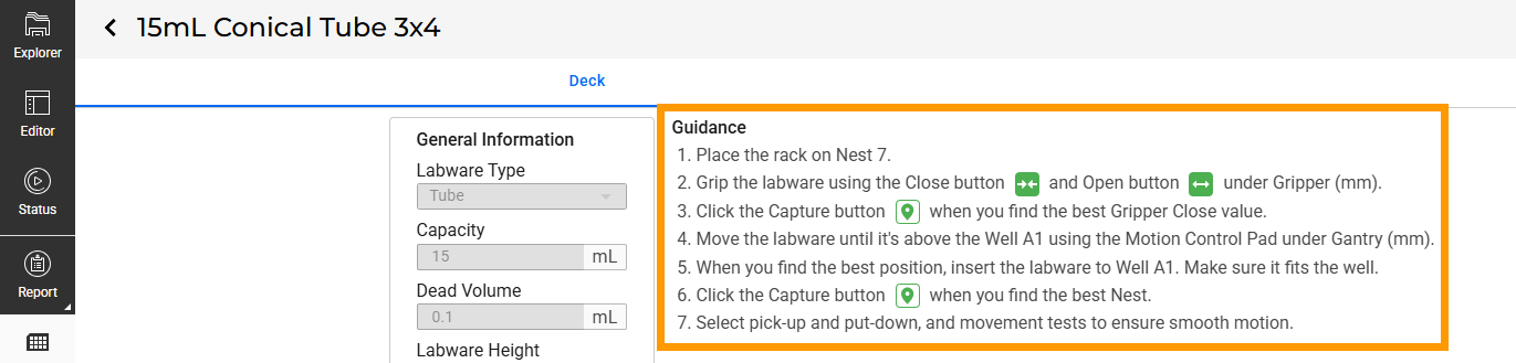
Guidance in the Deck Tab
Important
When calibrating the chip, ensure the transfer tubes are clear of obstacles before moving along the X or Y axes.
c. Always perform Pick and Place Test and Movement Test after calibration.
Go to the Station tab, and follow these steps:
a. Make sure the slider position on Station 1 is backward.
b. Put the required tube adapters on Station 1.
c. Follow the on-screen instructions to calibrate the tube or chip.
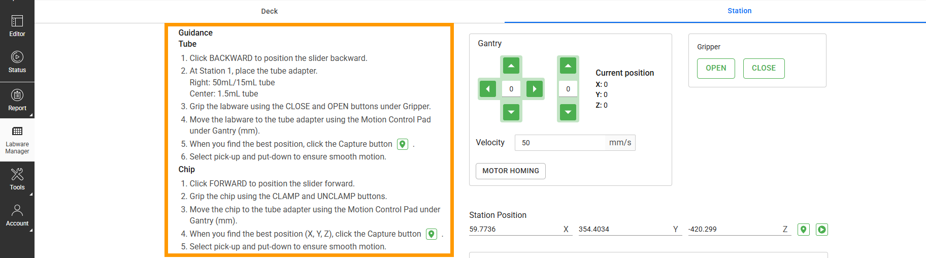
Guidance in the Station Tab
d. Always perform the Pick and Place Test after calibration.
Once the calibration is complete and the results are confirmed accurate, click SAVE.

Save Button