Instrument Overview
Before you set up the aµtoPULSE instrument, familiarize yourself with the instrument’s specifications, components, and accessories.
Specifications
Dimensions
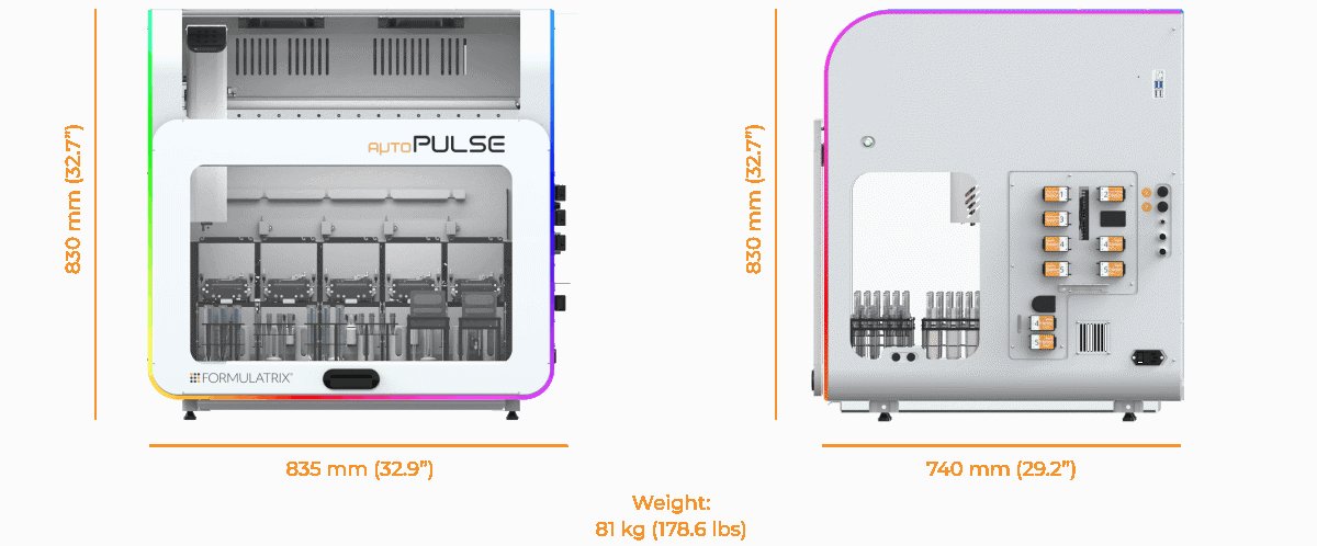
Instrument Dimensions
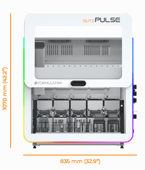
Instrument Dimensions (With Door Open)
Height with door closed: 830 mm (32.7”)
Height with door open: 1070 mm (42.2”)
Width: 835 mm (32.9”)
Depth: 740 mm (29.2”)
Weight: 81 kg (178.6 lbs)
Pressure and Vacuum Requirements
aµtoPULSE requires vacuum and pressure to actuate the chip’s diaphragm, liquid control valves, and each station’s clamp, supplied by the included FORMULATRIX Pump Box.
Electrical Requirements
Voltage Range: 100V-240V AC
Frequency Range: 50-60 Hz
Power: Max. 320 W
All outlet types are supported.
System Requirements
The following are the minimum system requirements to run the aµtoPULSE software.
Minimum |
Recommended |
|
|---|---|---|
Browser |
Google Chrome version 97 or later |
Latest Google Chrome version |
Screen Resolution |
1366 × 768 |
1920 × 1080 |
Screen Size |
11” |
14” |
Note
The instrument and the control device must be on the same network to connect.
Instrument Components
Front View
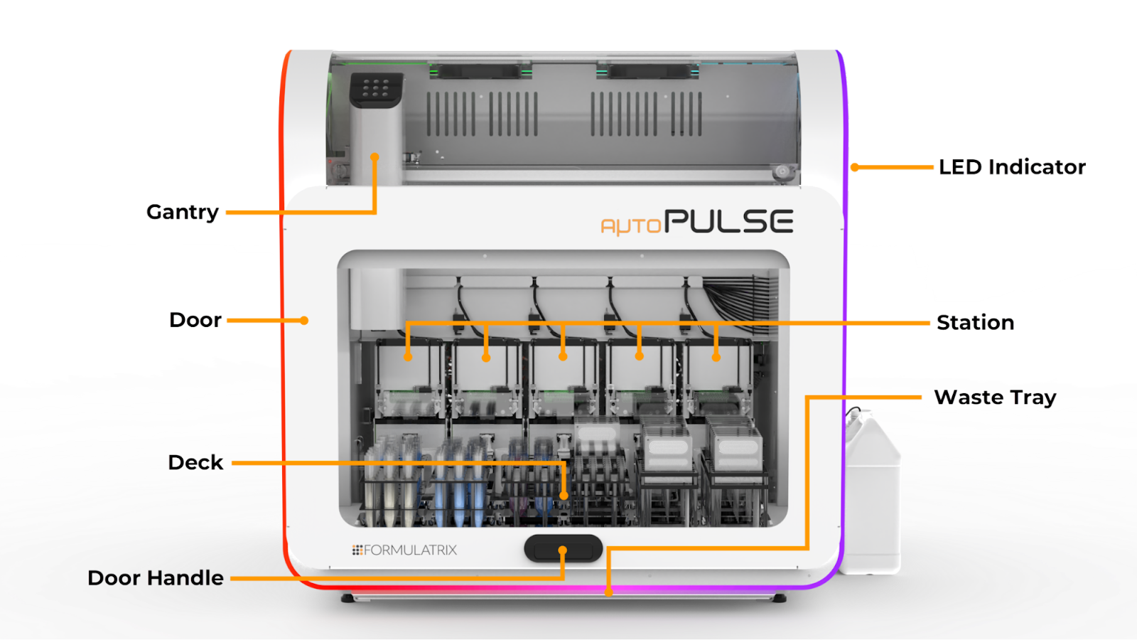
aµtoPULSE Front View
Gantry
The gantry moves tubes and chips during operation. It consists of the following main parts:
Gripper: Picks up, moves, and releases the tubes and chips between the station and the deck.
Arm: Controls the gripper movements and ensures proper alignment.
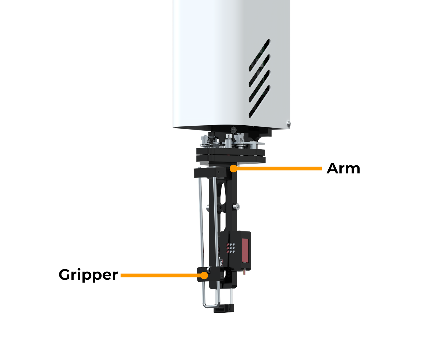
Arm and Gripper on the Gantry
Deck
The deck holds all the tubes and chips you need to run an experiment. It consists of 12 nests in which you can place the compatible tube racks and chip racks.
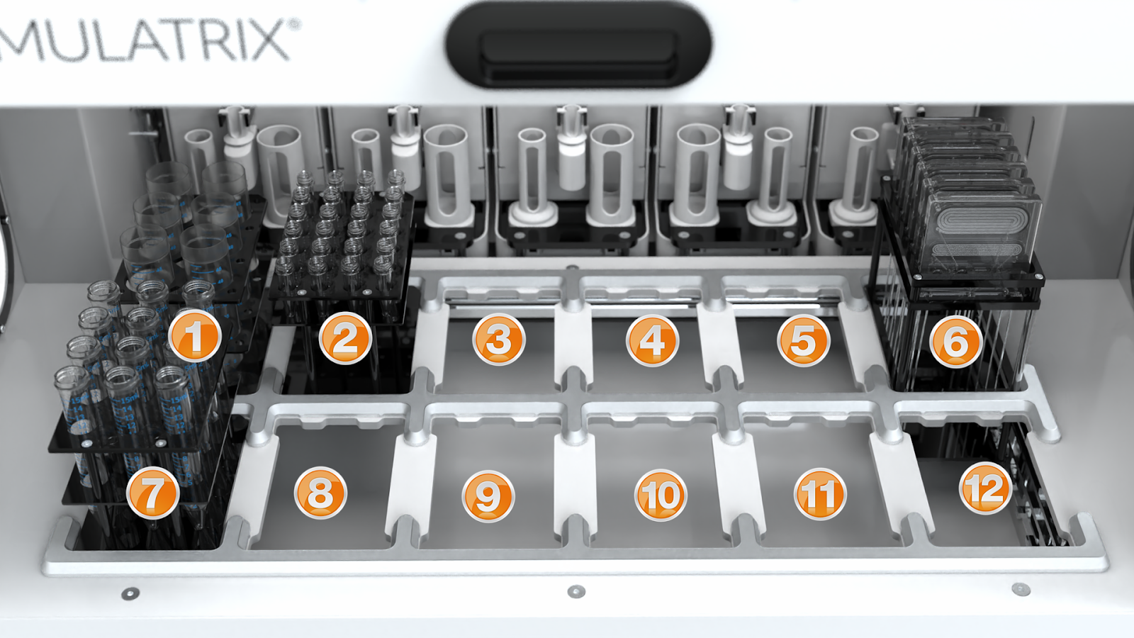
The aµtoPULSE Deck
Door
The door allows access to the internal components. For safety reasons, opening it during a protocol run will pause the gantry and trigger warning indicators in the Status Bar.
LED Indicator
The LED indicator displays various colors, each indicating a different instrument status during operation.
Color |
Description |
|---|---|
Blue |
aµtoPULSE is initializing. This may take a few seconds. |
| Rainbow | aµtoPULSE is idle. |
| White to Green | aµtoPULSE running a protocol. The indicator turns fully green when the protocol is complete. |
Yellow |
aµtoPULSE is paused. |
Red |
aµtoPULSE has encountered an error. |
Station
The 5 stations in aµtoPULSE support chip operation, liquid transfer, and volume measurement. Each station is connected to the peristaltic pumps on the instrument’s right side via peristaltic tubing.
There are five stations configured as a combination of Concentration and Cleaning stations (e.g., 3 Concentration and 2 Cleaning, or 4 Concentration and 1 Cleaning). Concentration stations perform sample concentration and buffer exchange, while Cleaning stations are dedicated to chip-cleaning.
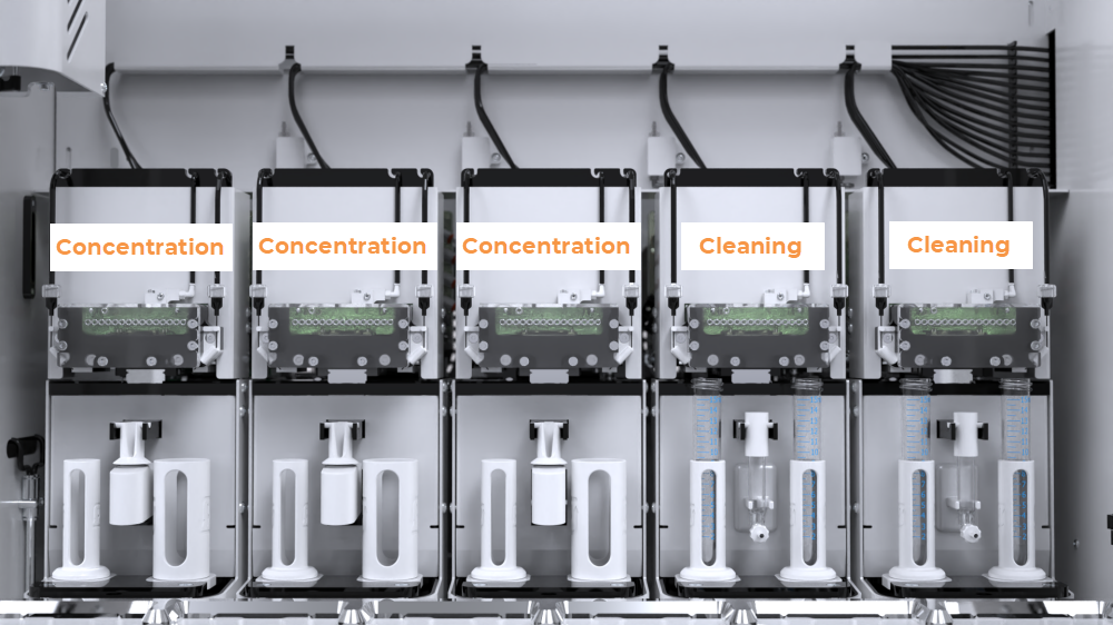
The aµtoPULSE Stations in a 3-2 Configuration
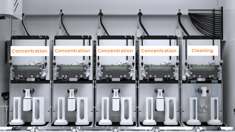
The aµtoPULSE Stations in a 4-1 Configuration
The Station’s key components include:
Base Chip: Connects with the chip’s valves and pumps to control the liquid from the instrument.
Chip Clamp: Holds the chip clamped during operation to ensure an airtight seal inside the chip.
Buffer Needle: Transfers buffer solution from the reservoir to the conical tube. The right buffer needle is inactive in Concentration Stations and only functions in the Cleaning Stations as a cleaning solution outlet.
Permeate Tubing Assembly: Facilitates the transfer of permeate liquid.
Scale: Measures the weight of the tubes and sample volumes using a load cell. The Conical Tube Scale is used for high-volume samples (in 50 and 15 mL conical tubes), while the Microtube Scale handles low-volume samples (in 1.5 mL microtubes).
Note
On the Cleaning Station(s), the center microtube scale is replaced by a drain to pump waste out.
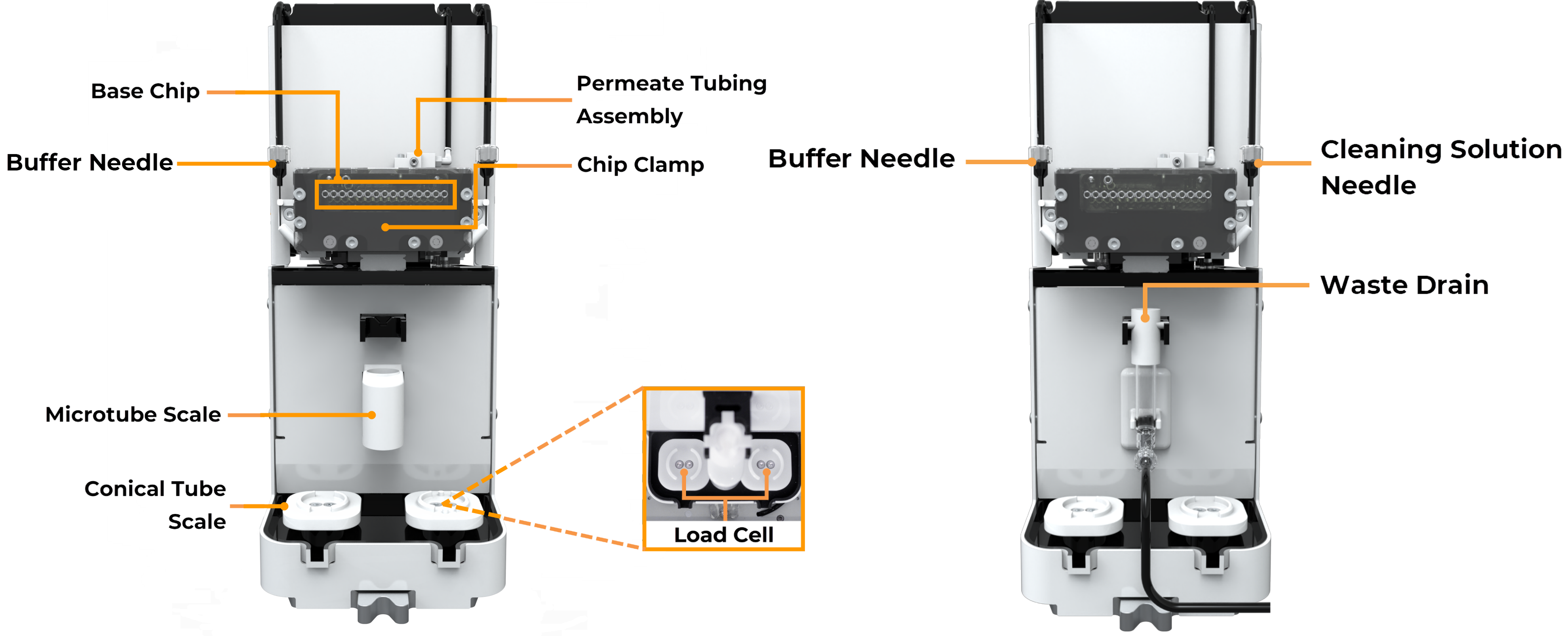
Components in the Concentration Station (Left); Components in the Cleaning Station (Right)
Waste Tray
The waste tray under the deck collects any spillover liquid. Pull it out to detach it from the instrument.
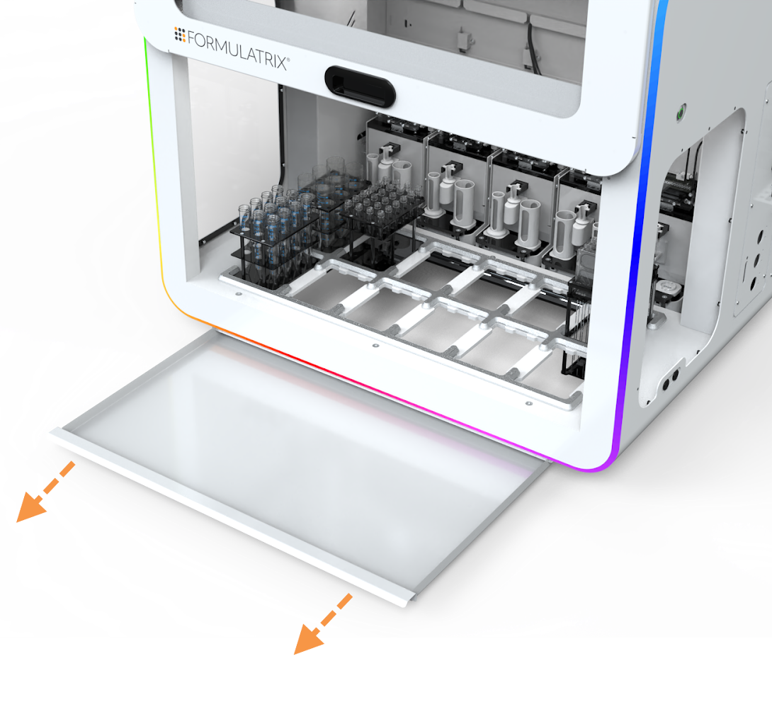
Waste Tray
Right Side View
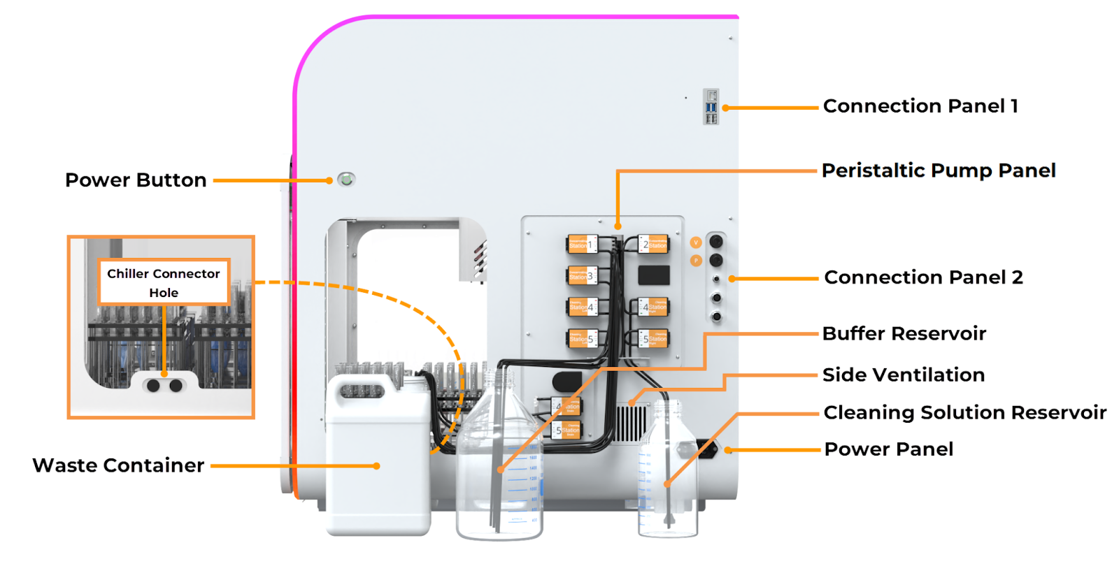
aµtoPULSE Right Side View
Power Button
The power button turns the instrument on and off. This button indicates various colors to indicate the following status and behavior:
Color |
Description |
|---|---|
Red (Blinking) |
The instrument is connected to the power source and is powering up. Wait until the power button turns solid red. |
Red (Solid) |
The instrument has been powered up and is ready for initialization. You can press the button to activate the instrument. |
Green (Blinking) |
The instrument is shutting down or initializing to connect with the software. |
Green (Solid) |
The instrument is active and connected to the software. |
Chiller Connector Hole Port
The chiller connector holes provide a pass-through for the chiller connectors to reach the cold pad on the deck.
Note
The Chiller set is an optional accessory. Contact FORMULATRIX support for installation.
Connection Panel 1
Ethernet Port: Connects the aµtoPULSE wired network to your computer.
USB Port: Provides a service interface used by support personnel for debugging and maintenance.
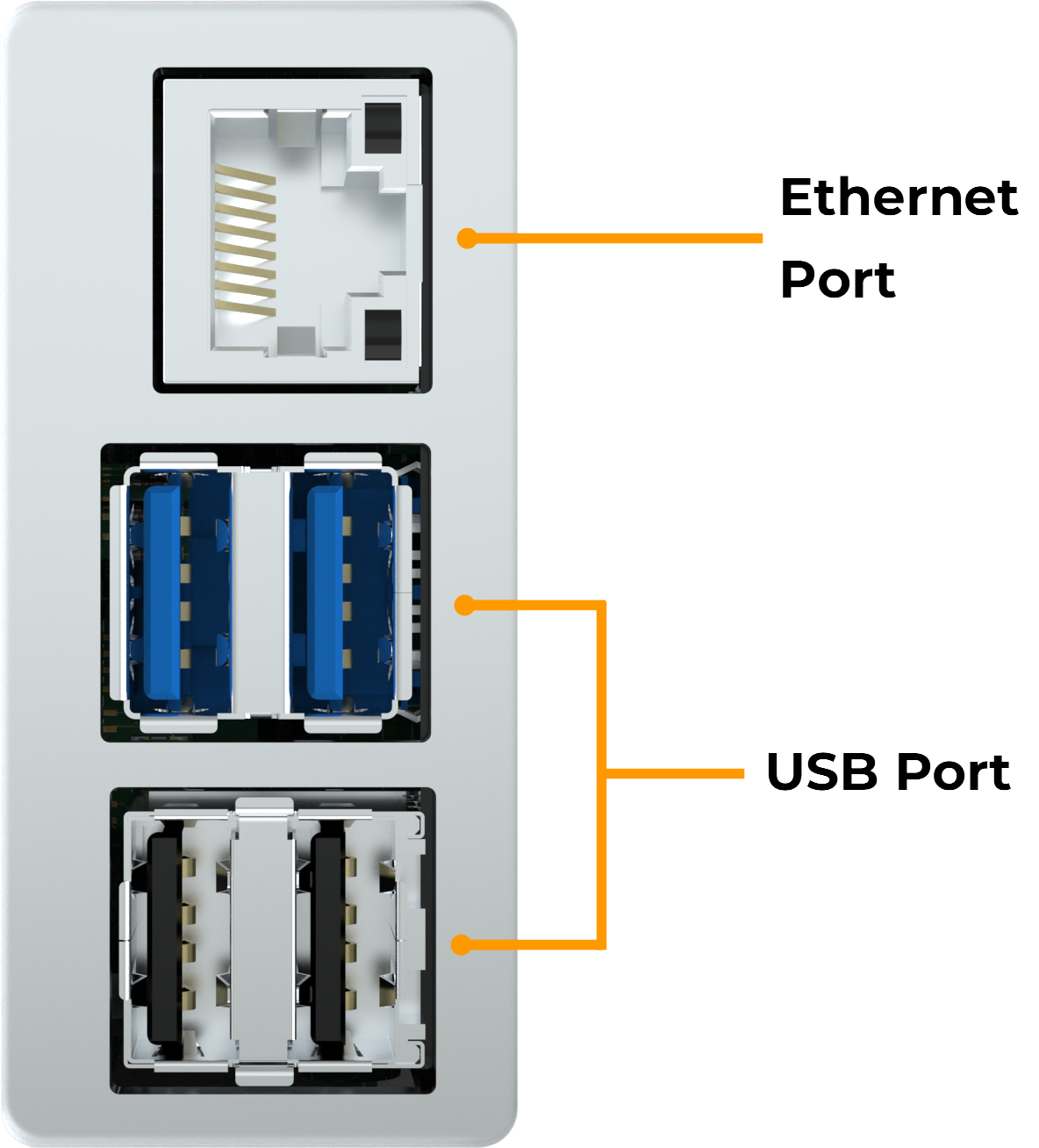
Ethernet Port and USB Port
Peristaltic Pump Panel
Concentration Station Pump: Each Concentrating Station’s pump transfers buffer from the reservoir to the left Buffer Needle of their respective stations.
Cleaning Station Pump: Transfers buffer and cleaning solutions from their reservoirs to the Buffer and Cleaning Solution Needles.
Waste Drain Pump: Transfers liquid from the Cleaning Station drains to the waste reservoir.
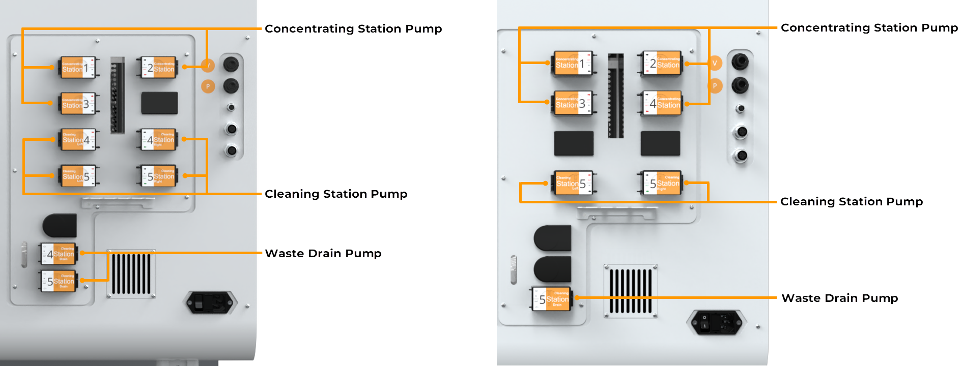
Components of the Peristaltic Pump Panel in 3-2 Configuration (Left); Components of the Peristaltic Pump Panel in 4-1 Configuration (Right)
Connection Panel 2
Pneumatic Port: Connects to the FORMULATRIX Pump Box for the required pressure and vacuum inputs. The ports are labeled P and V accordingly.
Waste Level Sensor Interface: Connects the instrument to the waste reservoir’s level sensor.
E-Stop Port: The optional emergency stop button connects to the E-stop ports to quickly stop the aµtoPULSE when necessary. Contact FORMULATRIX support for assistance with this feature.
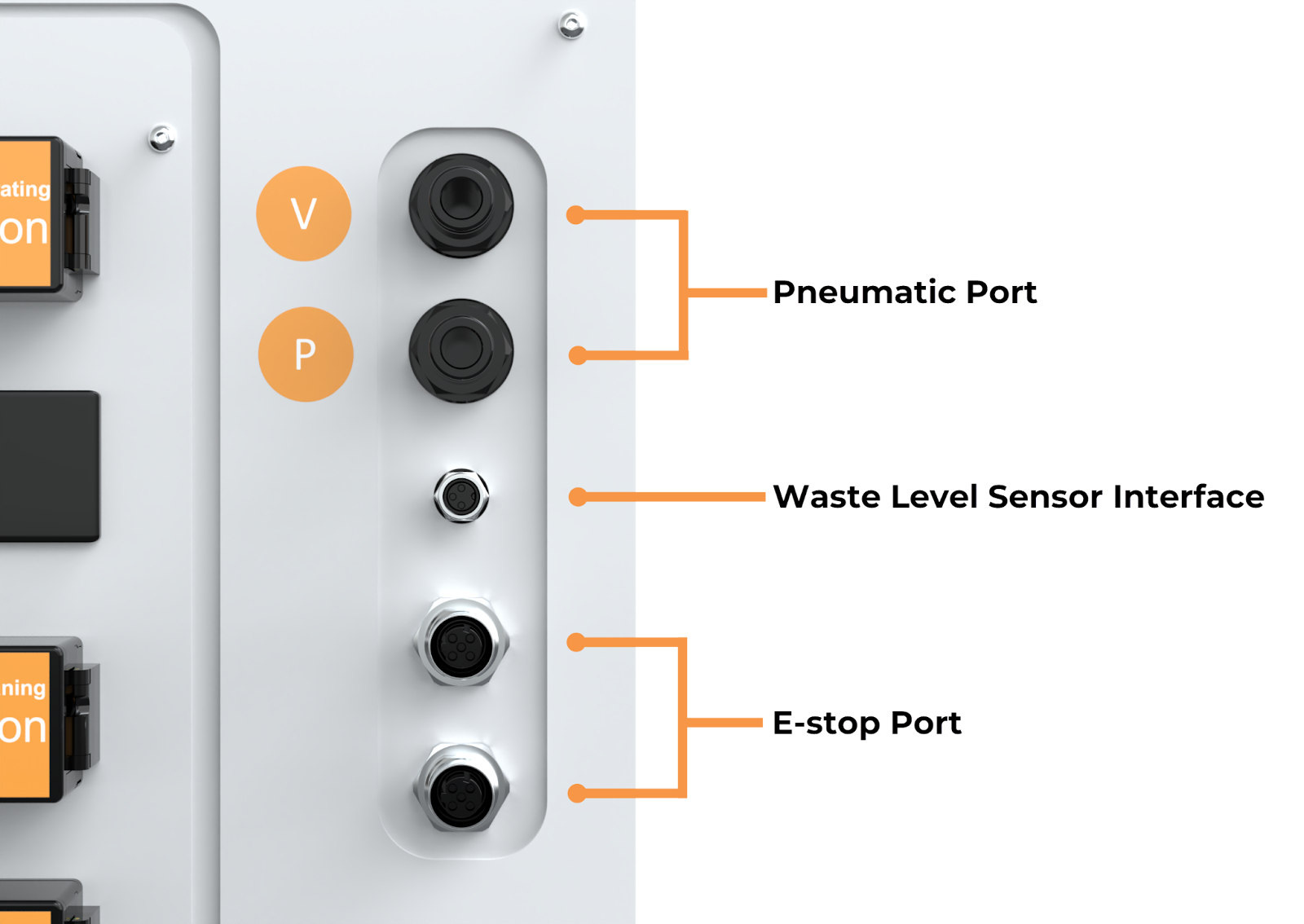
Pneumatic Port, Waste Level Sensor Interface, and E-Stop Port
Buffer Reservoir
The buffer reservoir holds buffer solution, used by the instrument when selected as the source.
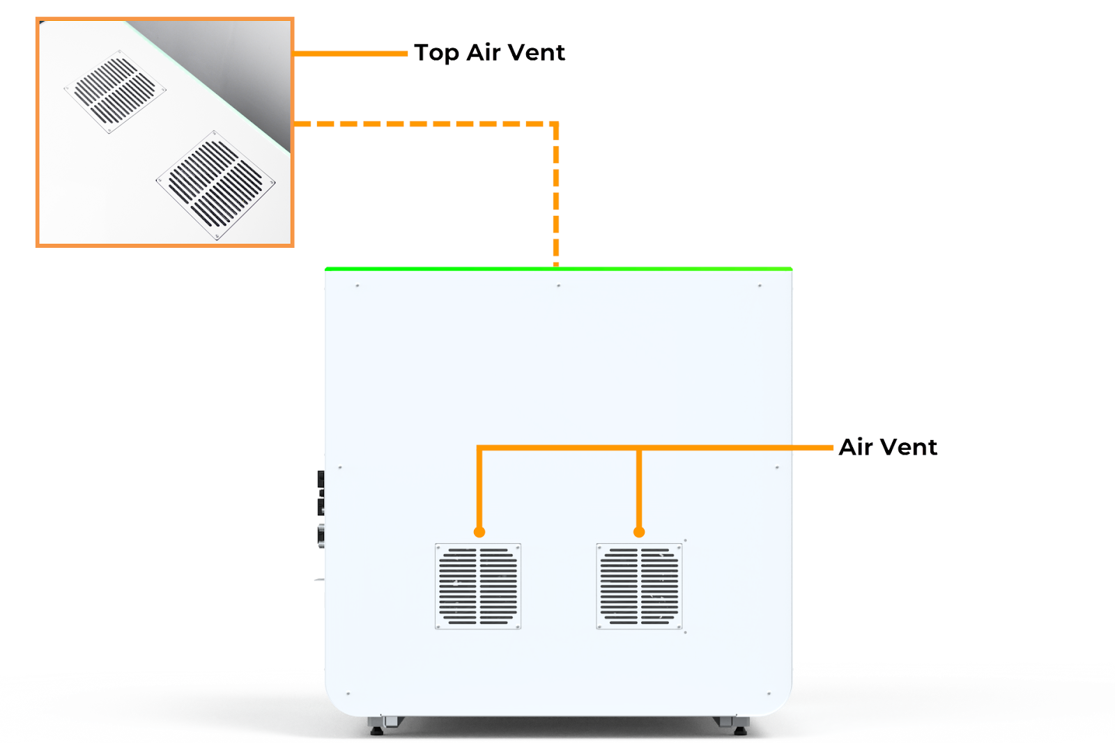
Side Vent
The side vent allows the power supply access to fresh air.
Cleaning Solution Reservoir
The cleaning solution reservoir holds cleaning solution, used by the instrument when the cleaning cycle is enabled.
Waste Container
The waste container collects waste permeate liquid from the instrument during the filtration process for safe disposal.
Power Panel
Power Switch: The power switch turns the instrument’s power on or off.
Power Entry: The power entry supplies the instrument with mains electricity.
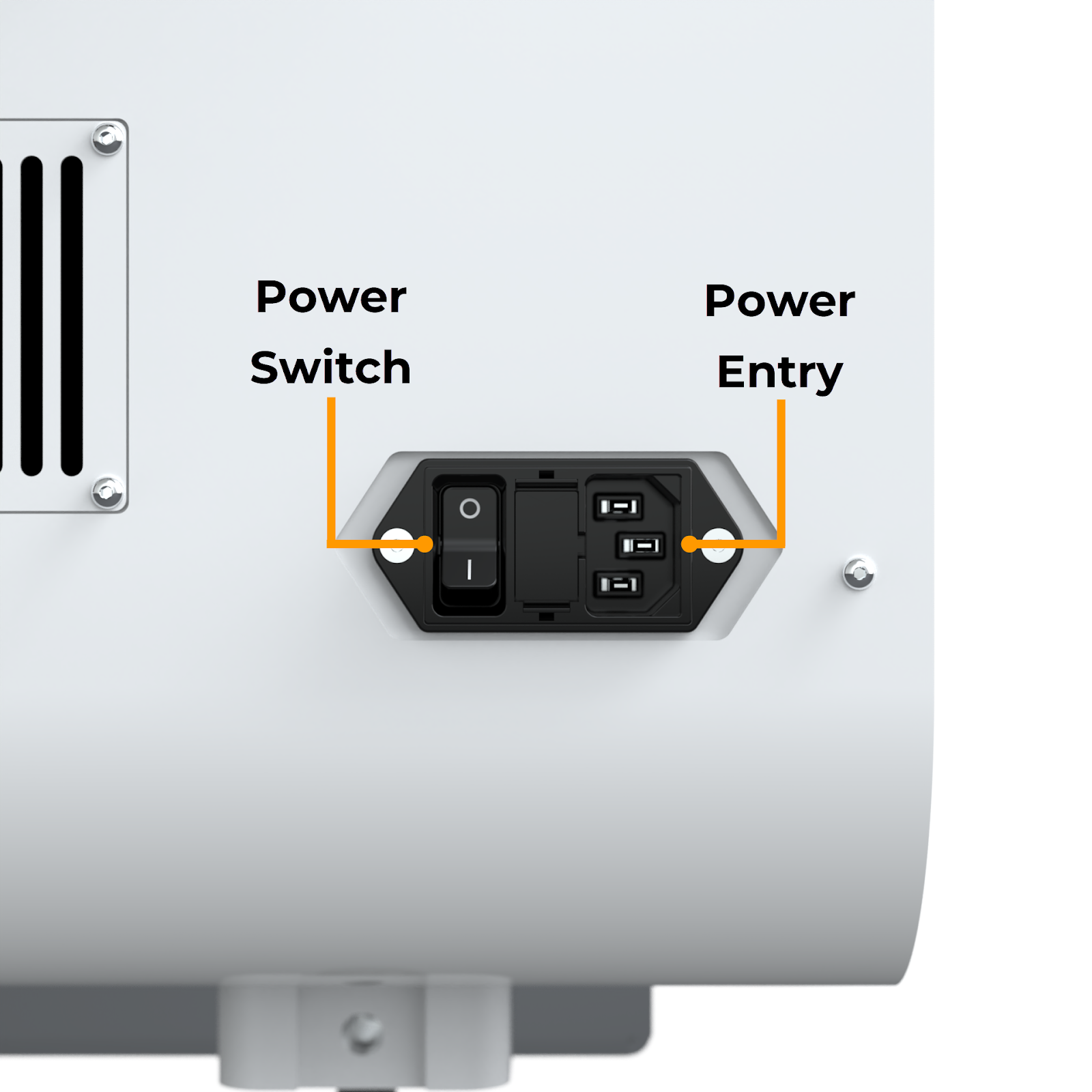
Power Switch and Power Entry
Chip and Labware
Chip Overview
Chips are the primary filtering device of aµtoPULSE. They come in two membrane material options and several MWCO options:
MWCO |
Membrane Material |
Membrane Material |
|---|---|---|
mPES |
RC |
|
5 kDa |
✔ |
✔ |
10 kDa |
✔ |
✔ |
30 kDa |
✔ |
✔ |
50 kDa |
✔ |
|
100 kDa |
✔ |
✔ |
300 kDa |
✔ |
The aµtoPULSE chip consists of the following parts:
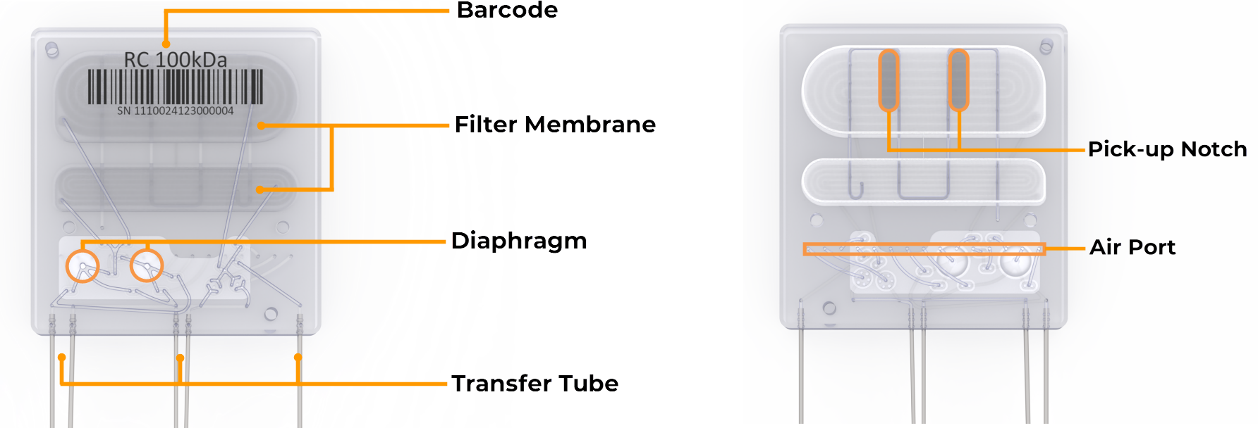
Chip Front View (Left); Chip Back View (Right)
Barcode
The barcode identifies the membrane material and its MWCO.
Filter Membrane
The filter membranes separate permeate from the sample, with both membranes (upper and lower) being used in high-volume filtration, while only the lower membrane is used for low-volume filtration.
Diaphragm
The two diaphragm pumps circulate the sample and buffer through the chip membrane.
Transfer Tube
The transfer tubes allow the sample and buffer to flow into and out of the chip from the tubes.
Pick-up Notch
The pick-up notch ensures the correct gripper position when picking up the chip.
Air Port
The chip air port receives air flow from the instrument, actuating the diaphragm pump and control valves to control the liquid flow.
Labware Overview
Tube Adapter
The tube adapters allow the sample and buffer tubes to rest securely on the scales, providing accurate weight values for the instrument.
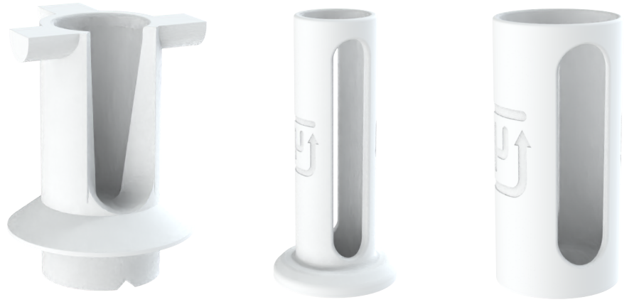
1,5 mL Microtube Adapter (Left); 15 mL Tube Adapter (Center); 50 mL Tube Adapter (Right)
Conical Tube
The conical tubes hold sample and buffer in two capacities: 15 mL and 50 mL.
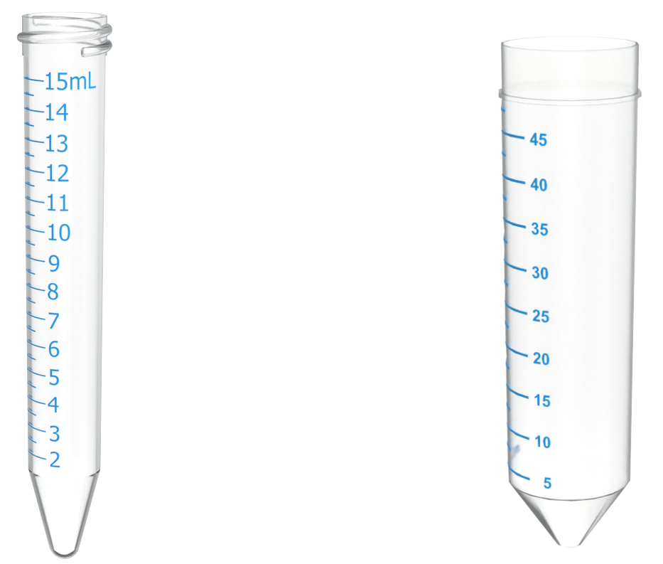
15 mL Conical Tube (Left); 50 mL Conical Tube (Right)
Microtube
The microtube holds 1.5 mL of sample and is primarily for small-volume operations.
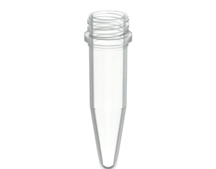
1,5 mL Microtube
Important
To prevent any misalignment or collision, make sure to use a proper microtube with no caps.
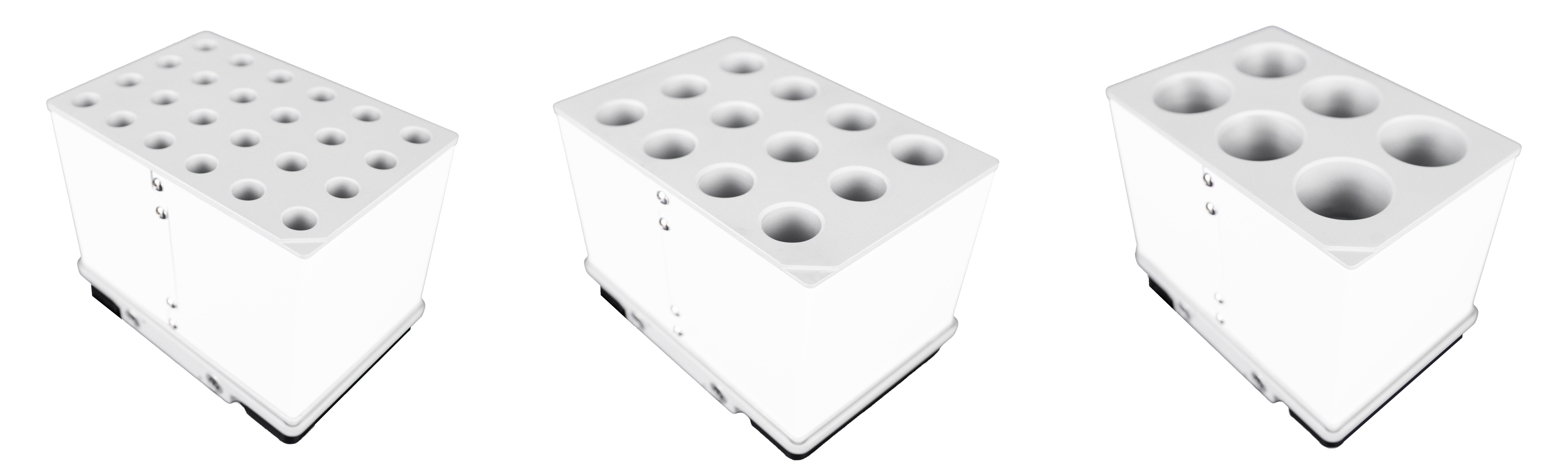
Tube Rack
The tube rack holds your tubes and comes in 3 sizes:
4x6 1.5 mL Microtube Rack (24 microtubes)
3x4 15 mL Conical Tube Rack (12 tubes)
2x3 50 mL Conical Tube Rack (6 tubes)
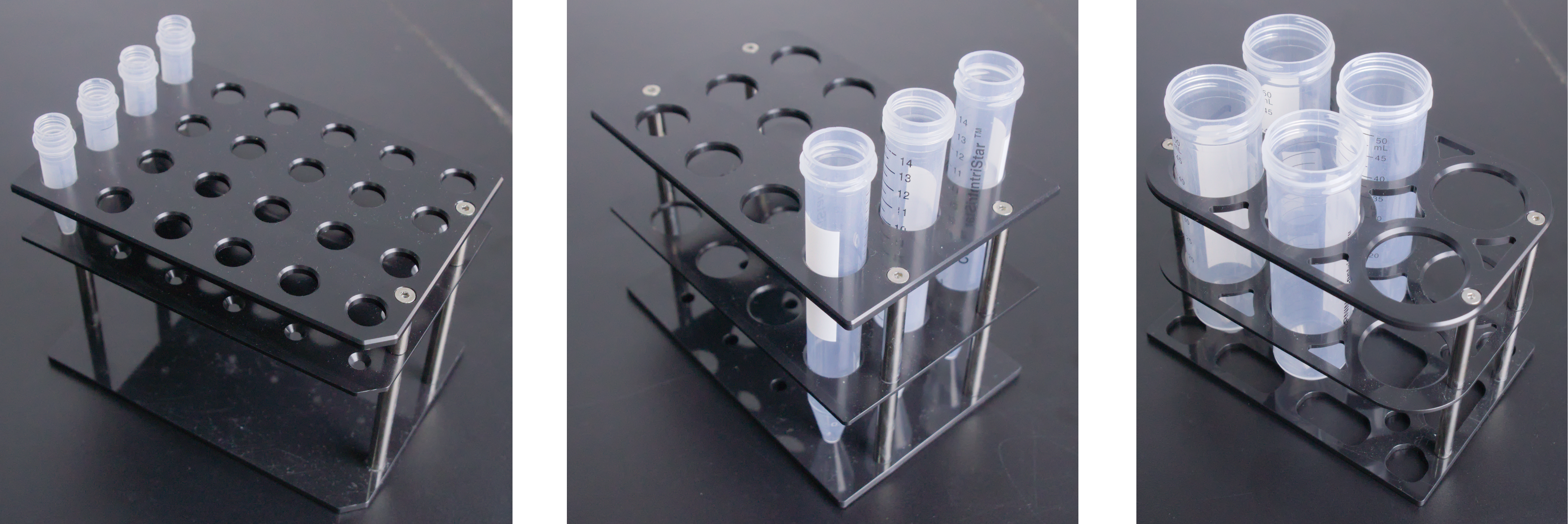
1,5 mL Microtube Rack (left); 15 mL Tube Rack (Center); 50 mL Tube Rack (Right)
Chip Rack
The chip rack accommodates six chips and features a built-in alignment design for easier and correct placement.
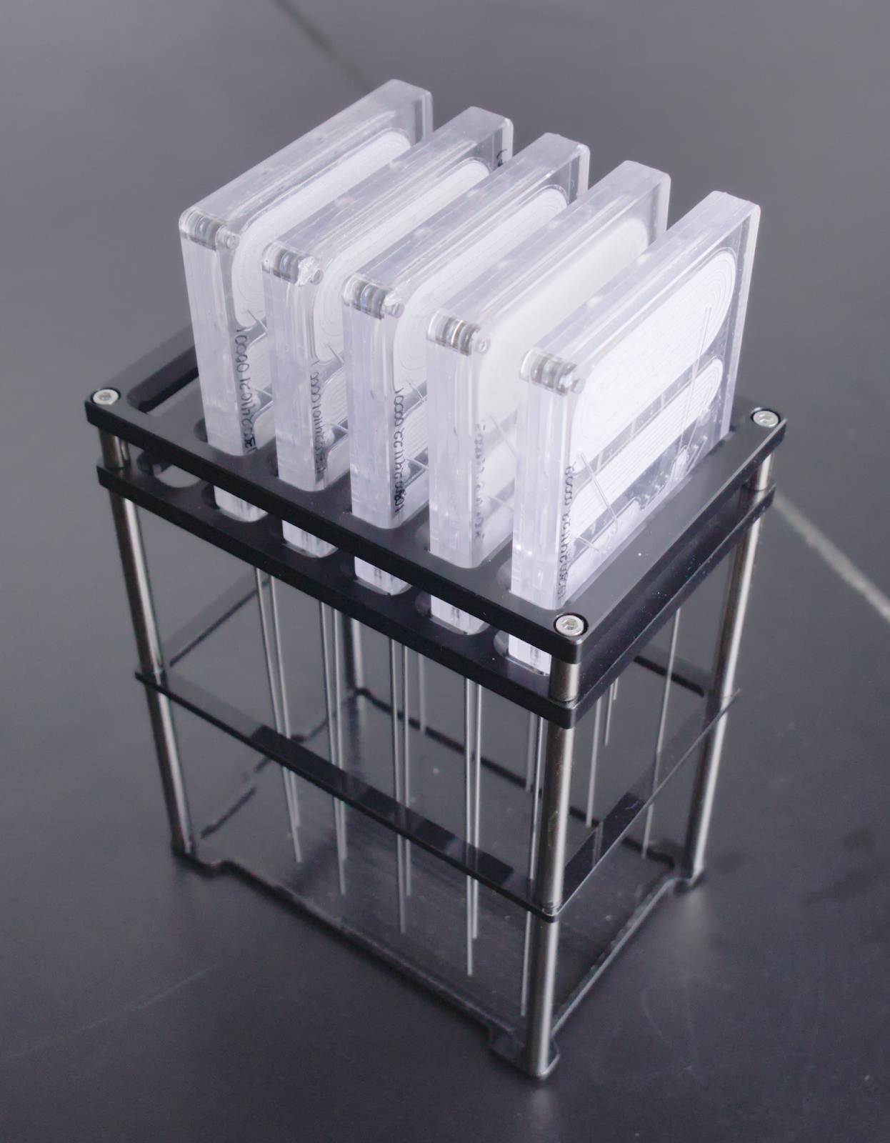
Chip Rack
Note
To purchase aµtoPULSE chip and other accessories, contact sales@formulatrix.com.
Cooling Rack
The Cooling Rack is an optional accessory installed by the support team upon request. It maintains low temperatures during the workflow to preserve sample integrity and ensure consistent results for temperature-sensitive samples. It is compatible with:
1.5 mL microtubes
15 mL conical tubes
50 mL conical tubes
1,5 mL Microtube Cooling Rack (Left); 15 mL Conical Tube Cooling Rack (Center); 50 mL Conical Tube Cooling Rack (Right)
- Related Topics: