User Manual
This manual provides basic information and instructions to help you set up and operate aµtoPULSE for the first time.
Warning Indications and Symbols
|
Caution |
Read the manual before operating this equipment. No user serviceable parts. Only qualified service personnel shall service this equipment. |
|
Electric Shock Hazard |
Danger High Voltage - Disconnect all sources before servicing. |


Knowing the aµtoPULSE Accessories
We provide an accessory kit that includes everything you need to get started, contained in several places inside the packaging, including:
| No. | Item Description | QTY | UoM |
|---|---|---|---|
| Inside the Instrument | |||
| 1. | 2.5 gal (10 L) Waste Container | 1 | Ea |
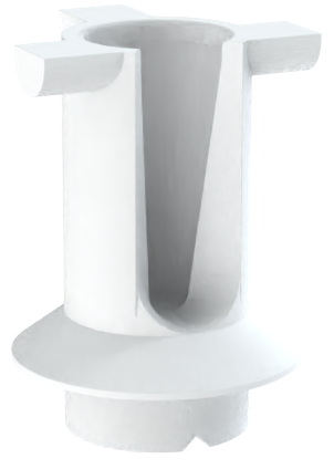
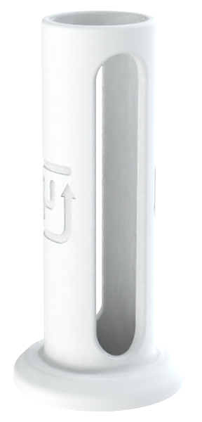
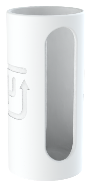
| 2. | 1.5 mL Tube Adapter | 5 | Ea |
| 3. | 15 mL Tube Adapter | 10 | Ea |
| 4. | 50 mL Tube Adapter | 8 | Ea |
| Inside the Kit Foam | |||
| 5. | 1.5 mL Tube Rack | 2 | Ea |
| 6. | 15 mL Tube Rack | 2 | Ea |
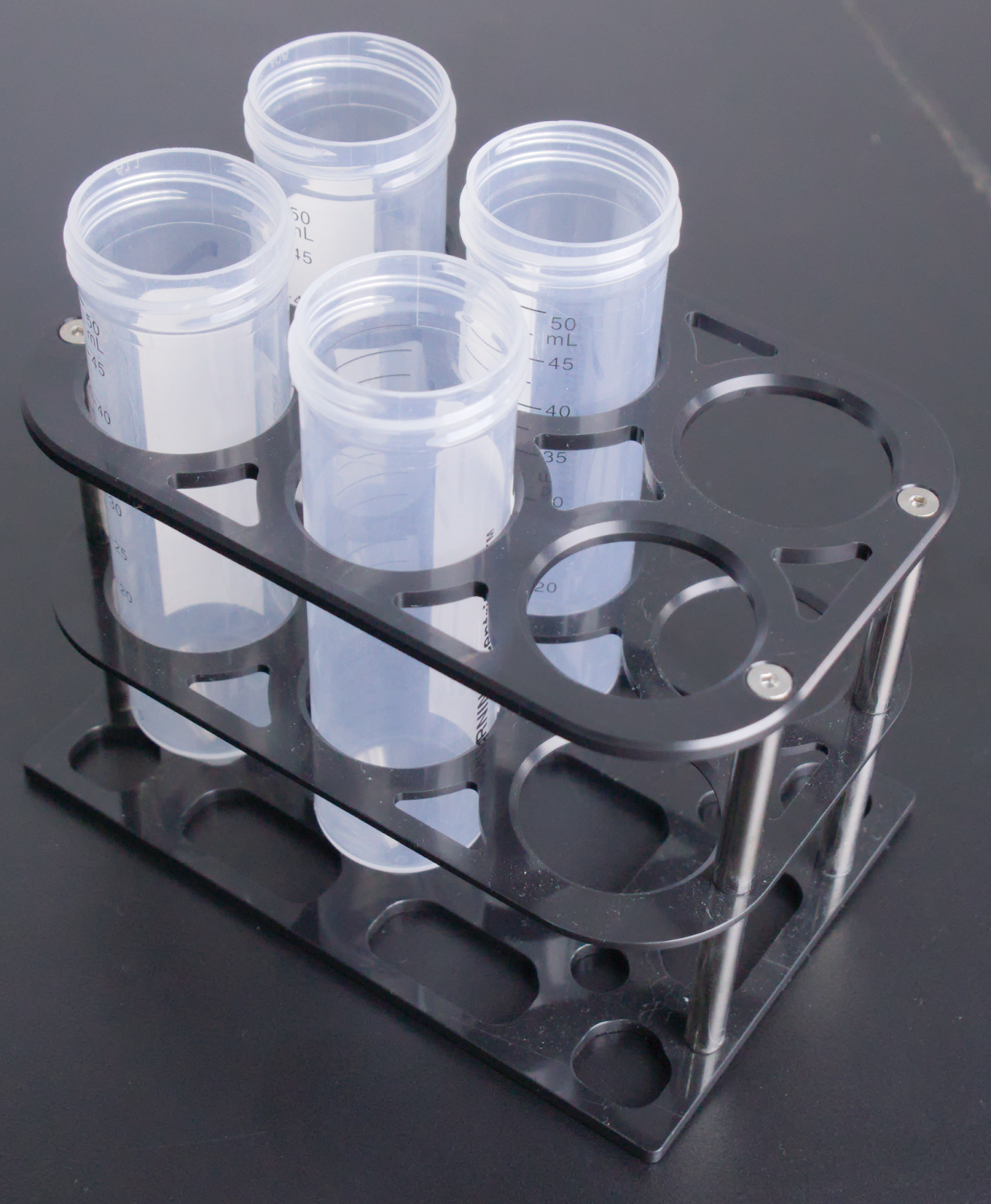
| 7. | 50 mL Tube Rack | 3 | Ea |
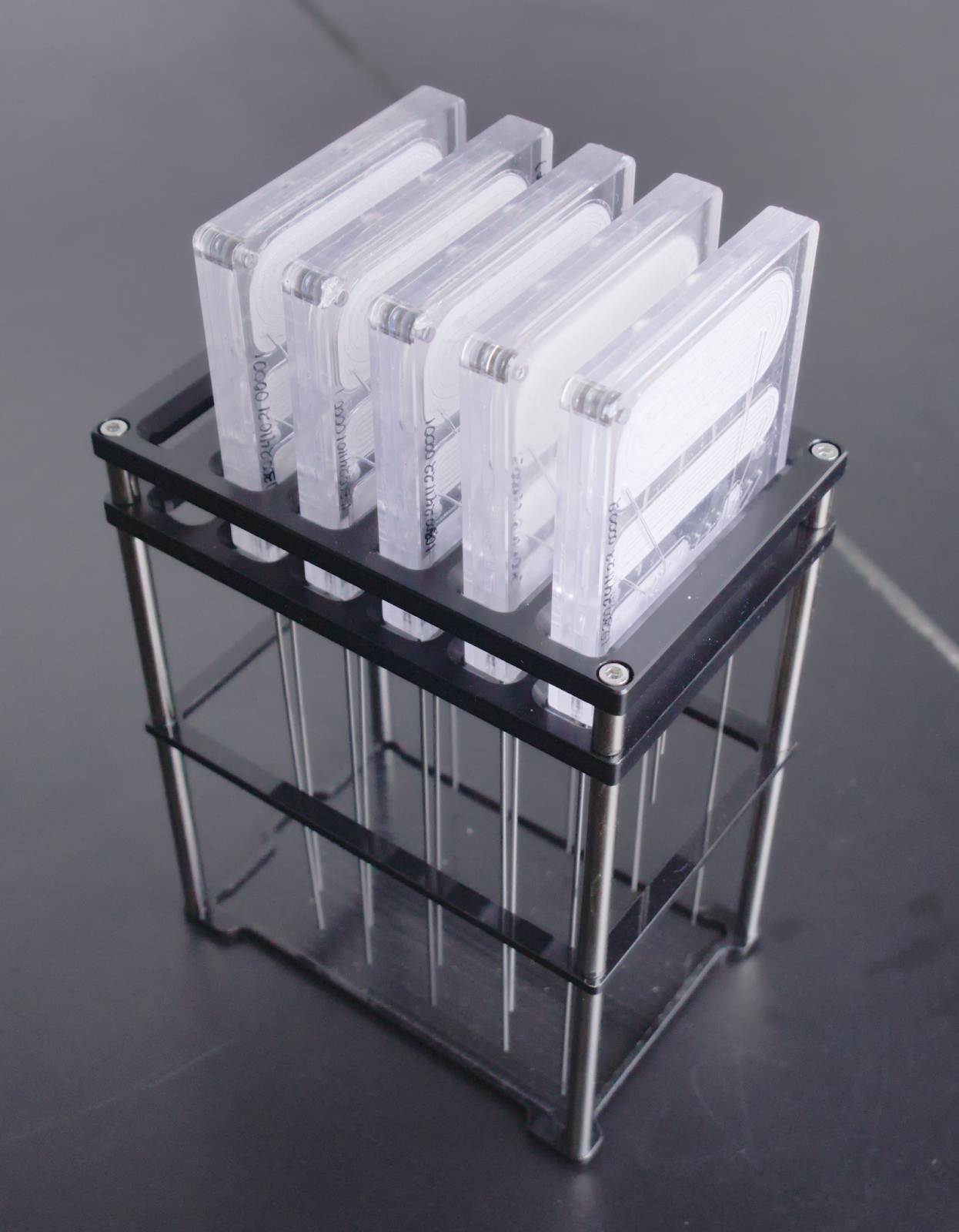
| 8. | Chip Rack | 5 | Ea |
| 9. | Servicing Toolkit | 1 | Ea |
| 10. | Chip Starter Kit (Pack of 6) | 1 | Pack |
| In the Kit Box | |||
| 11. | 1.5 mL Conical Tubes | 6 | Ea |
| 12. | 15 mL Conical Tubes | 6 | Ea |
| 13. | 50 mL Conical Tubes | 6 | Ea |
| 14. | 10 g Calibration Weight | 2 | Ea |
| 15. | 100 g Calibration Weight | 1 | Ea |
| 16. | SIM Card Ejector | 1 | Ea |
| 17. | Ethernet Cable | 1 | Ea |
| 18. | Ethernet Adapter | 1 | Ea |
| 19. | Capacitive Sensor | 1 | Ea |
| 20. | Lifting Handle Toolkit | 1 | Ea |
| 21. | Long Base Chip Gasket | 5 | Ea |
| 22. | Single Base Chip Gasket | 10 | Ea |
| 23. | Buffer Needle | 10 | Ea |
| 24. | Peristaltic Tube Assembly | 1 | Ea |
| 25. | 25 ft Peristaltic Pump Tubing | 2 | Ea |
| 26. | Country-specific Power Cord based on region | 1 | Ea |
| For Customers Located in China | |||
| 27. | Installation Certificates | 1 | Ea |
| 28. | Warranty Letters | 1 | Ea |
Identifying the aµtoPULSE Components
Front View
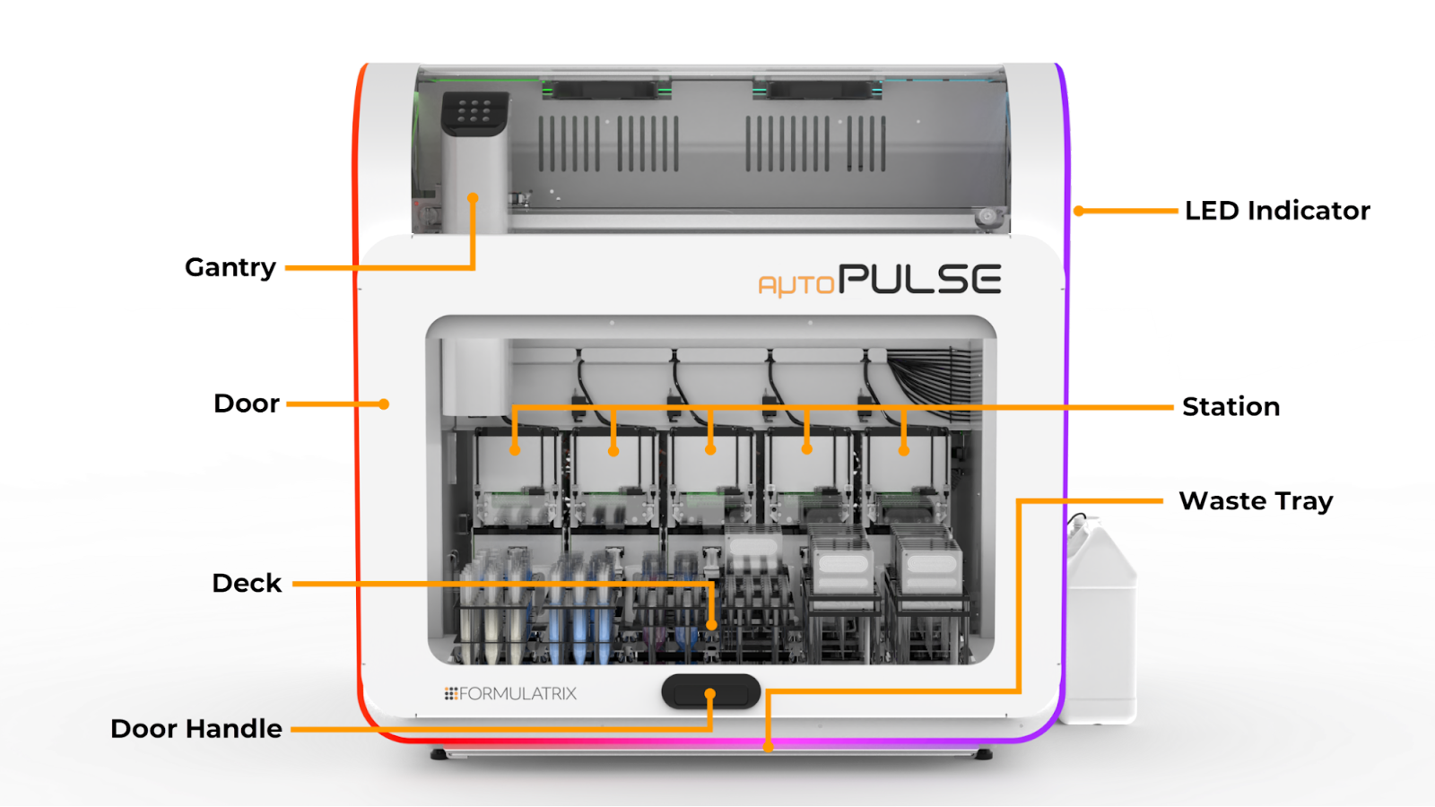
aµtoPULSE Front View
Gantry: Moves the tubes and chips with the Gripper handling placement and the Arm directing the gripper for accurate positioning.
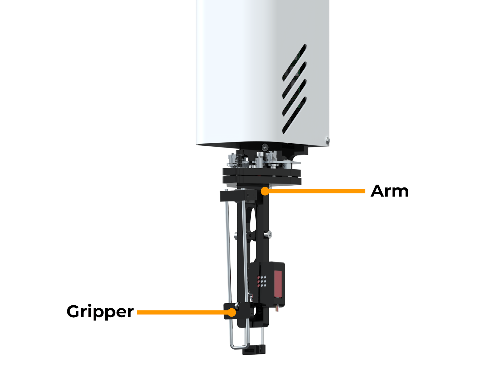
Gripper and Arm
Door: Allows access to internal components and ensures safety during operation by stopping the gantry if opened during active runs.
Deck: Holds the labware and chips needed to run an experiment, containing 12 nests for compatible racks.
LED Indicator: Indicates different instrument statuses during operation. For example, multi-color: aµtoPULSE is idle, white to green: running a protocol, red: an error has occurred, etc. See Instrument Overview for detailed information
Waste Tray: Collects any spilled liquid during protocol runs.
Important
If you find liquid in the tray due to a system error, check the source of the leak and contact support@formulatrix.com.
Station (as a whole unit): Serves as the main component for running protocols. The station components include:
Concentration Station
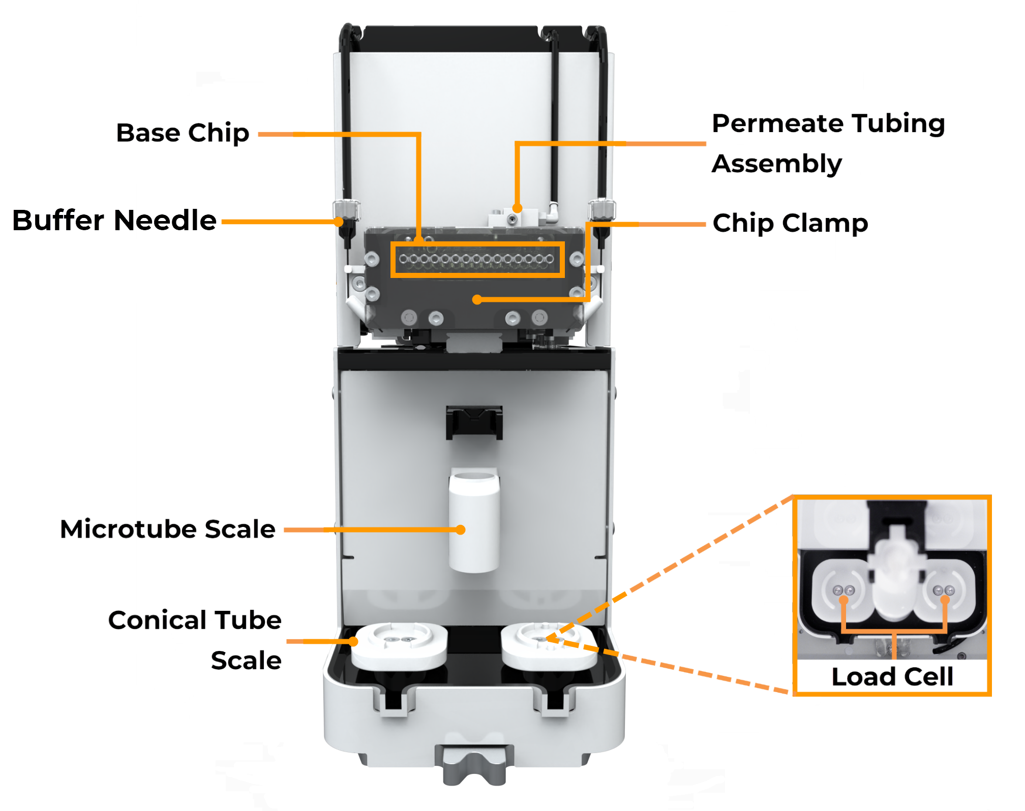
Concentration Station Components
Base Chip: Connects with the chip’s air receiver to supply the chip with air from the instrument.
Buffer Needle: Transfers buffer solution from the reservoir to the conical tube.
Microtube Scale: Measures the weight of small-volume samples (1.5 mL).
Conical Tube Scale: Measures the weight of high-volume samples (50 and 15 mL).
Permeate Tubing Assembly: Facilitates the transfer of permeate liquid.
Chip Clamp: Holds the chip securely in place during the operation to ensure an airtight seal inside the chip.
Cleaning Station
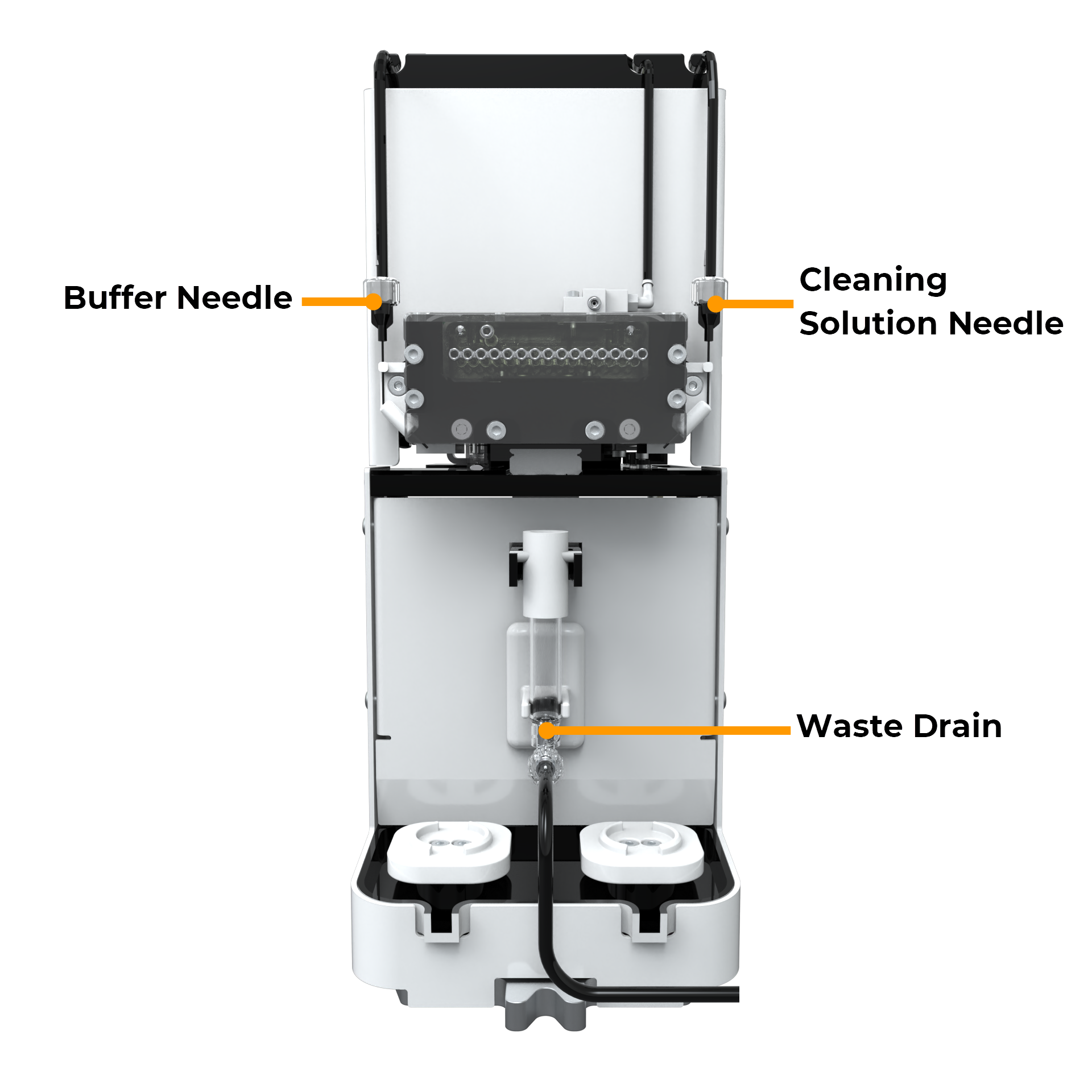
Cleaning Station Components
Cleaning Solution Needle: Transfers cleaning solution from the reservoir to the conical tube.
Waste Drain: Transfers waste liquid out to the waste container.
Right Side View
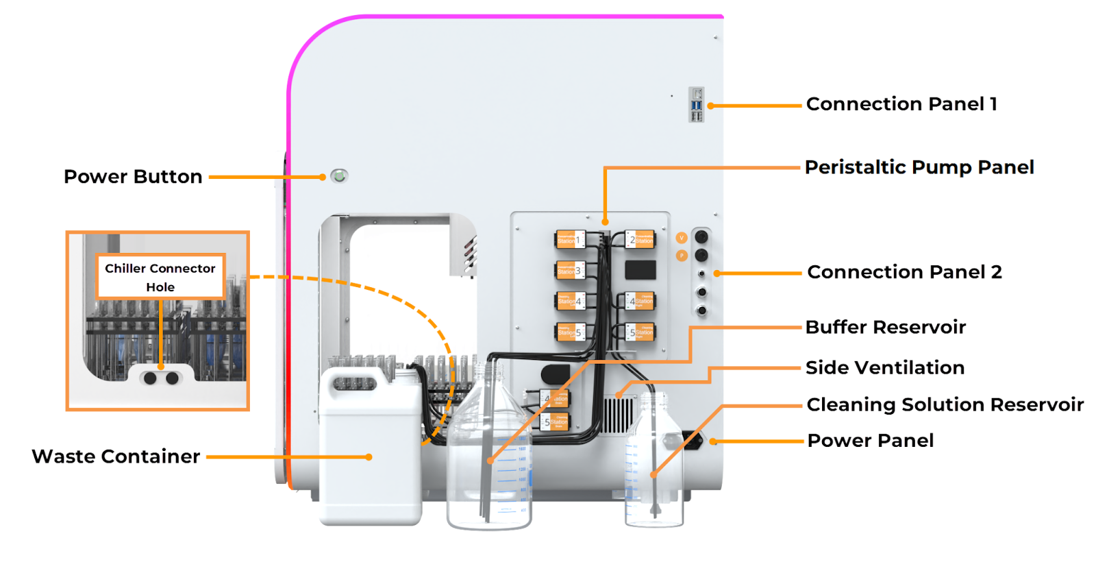
aµtoPULSE Right Side View
Power Button: Press the button to power on or off the instrument. Refer to Instrument Overview to identify the LED indicator on the button.
Chiller Connector Hole: Provides a pass-through for the chiller connectors to reach the cooling rack on the deck.
- Connection Panel 1:
Ethernet Port: Connects the aµtoPULSE wired network to your computer.
USB Port: Provides a service interface used by support personnel for debugging and maintenance.
Peristaltic Pump Panel: Peristaltic pumps move buffer and cleaning solutions through the system. Each Concentration Station uses one pump, while the Cleaning Station uses two pumps plus a dedicated Waste Drain pump. See Instrument Overview for more information.
- Connection Panel 2:
Pneumatic Ports: Connect to the FORMULATRIX Pump Box to supply the required pressure and vacuum.
Waste Level Sensor Interface: Connects the instrument with the waste reservoir’s level sensor.
E-Stop Port: Connects to the optional FORMULATRIX emergency stop button for quick instrument shutdown.
Buffer Reservoir: Stores buffer solution needed during profile runs.
Side Vent: Allows the power supply to draw in fresh air.
Cleaning Solution Reservoir: Stores cleaning solution needed during cleaning cycles.
Waste Container: Collects waste permeate from the instrument.
- Power Panel:
Power Entry: Plug in the power cable to supply power to the system.
Power Switch: Switches power to the instrument.
Back View
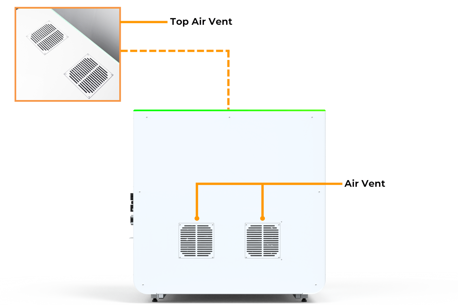
aµtoPULSE Back View
Air Vent: Draws air inside, then exhausts it from the top to maintain operating temperature.
Chip and Labware
aµtoPULSE Chip
Chips are the filtering device of aµtoPULSE with the following components.
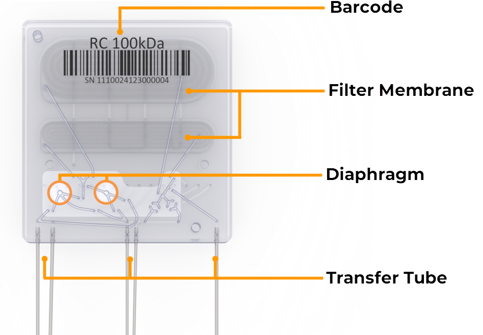
aµtoPULSE Chip Front View
Barcode: Identifies the membrane material and its MWCO.
Filter Membrane: Separates permeate from the sample, with both membranes (upper and lower) used in high-volume filtration and only the lower membrane for low-volume filtration.
Note
The membrane options are available on mPES and RC, expanding flexibility in filtration workflows. See Chip Overview for details.
Diaphragm: The two diaphragms circulate the sample and buffer through the chip’s membrane.
Transfer Tube: Allows liquid to flow across the chip from the tubes.
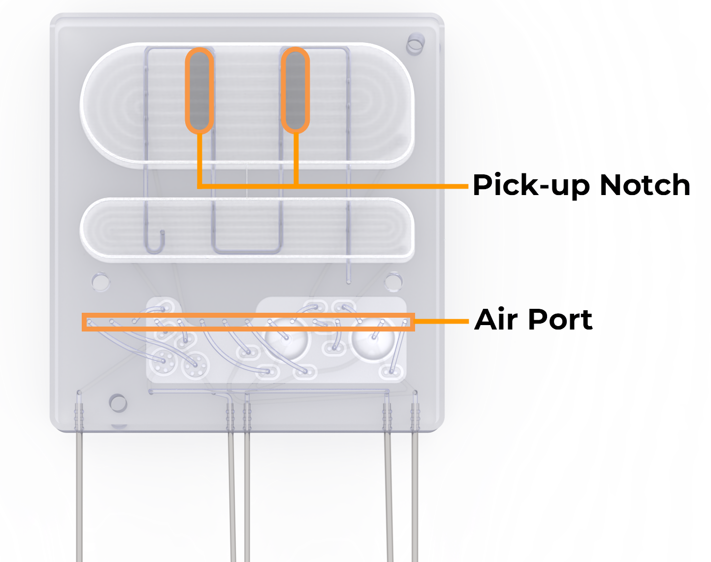
aµtoPULSE Chip Back View
Pick-up Notch: Ensures correct gripper position when picking up the chip.
Air Port: Receives air flow from the instrument, actuating the diaphragm pump and control valves to control the liquid flow.
Labware
Item |
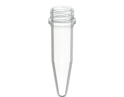
1.5 mL Microtube |
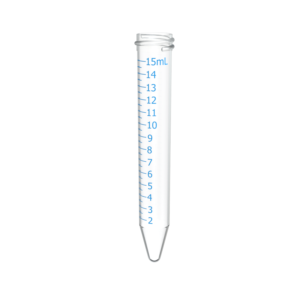
15 mL Conical Tube |
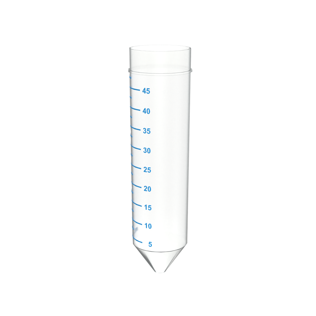
50 mL Conical Tube |
|---|---|---|---|
Tube Adapter |
|
|
|
Tube |
|
|
|
Tube Rack |
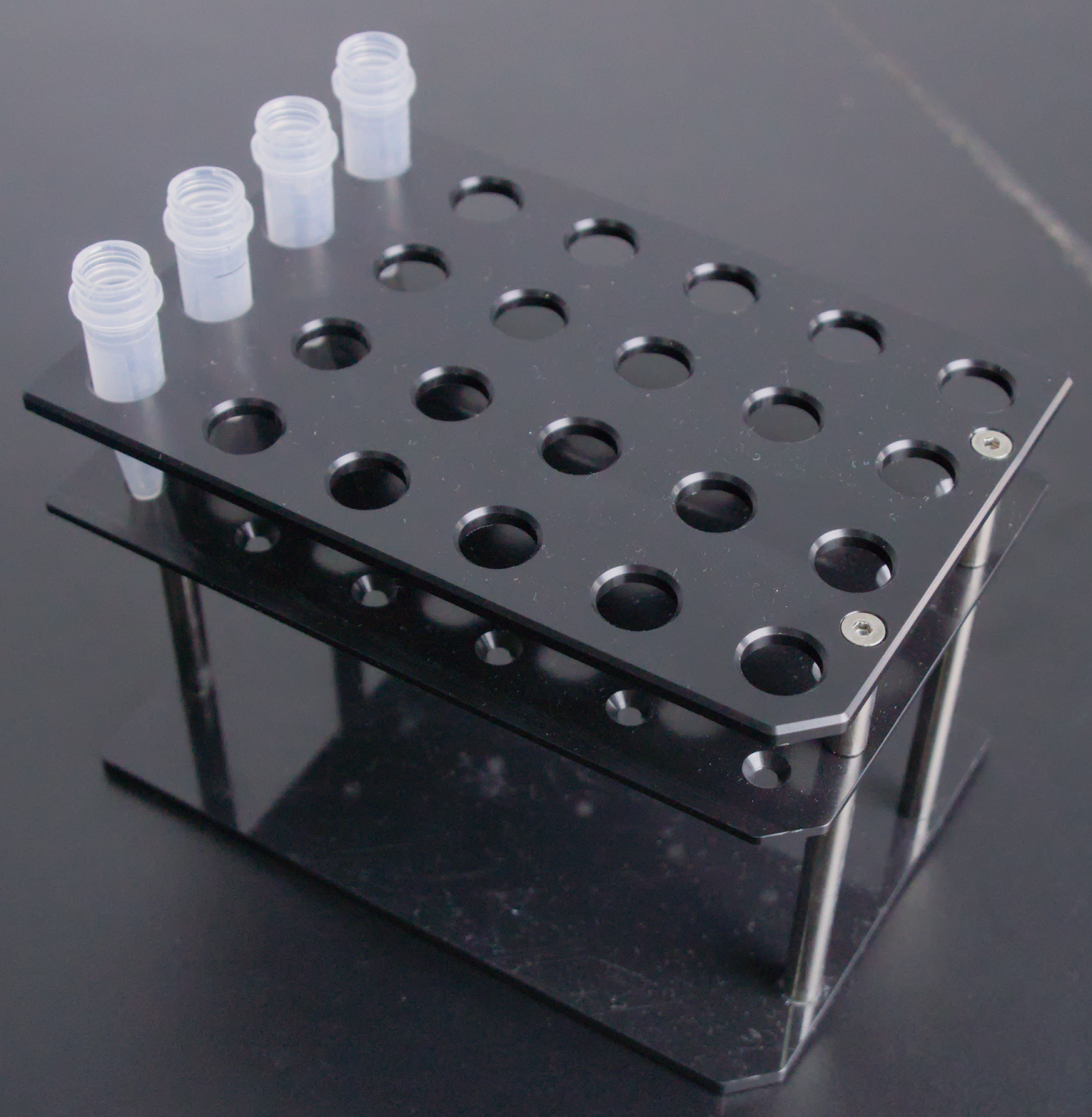
|
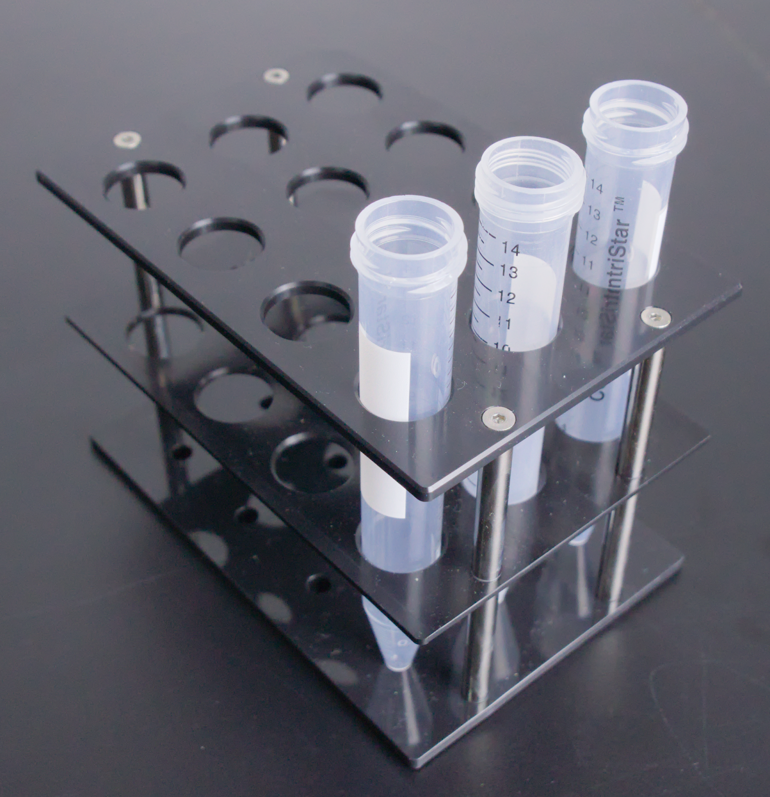
|
|
Chip Rack |
|
||
Using the aµtoPULSE Software
Log in to the aµtoPULSE Software
Open the aµtoPULSE software from your browser by typing:
http://autopulse-[device serial #].localE.g., http://autopulse-4.local for instrument AP-1-0004.Enter your username and password to log in.
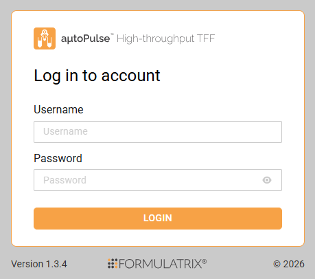
aµtoPULSE Software Login
Understanding the aµtoPULSE Software
In the aµtoPULSE software, navigate through the pages to run protocols and operate the instrument. The basic pages are described below.
Explorer
Open the Explorer page to view, open, add, and manage protocols. All defined protocols are listed on this page.
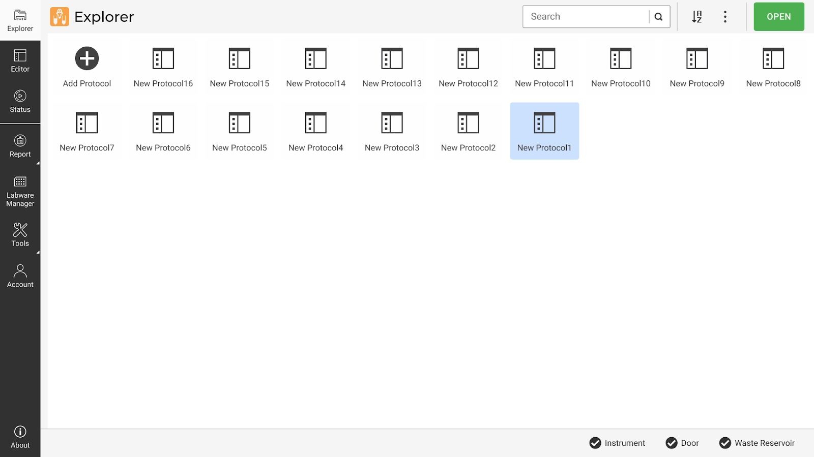
Explorer Page
Editor
The Editor page is where you define labware and create profiles for your protocols. Identify the sections from the description below.
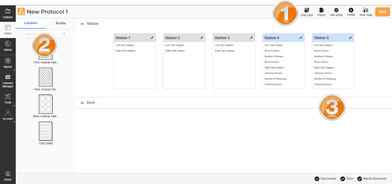
Editor Page
Section 1: Command Bar
Note
The protocol name is editable. Click on it to rename.
Chip Cleaning
 : Clean batches of chips and sync the chip selection with the current protocol configuration.
Import
 : Upload the labware and profile data file for a quick protocol setup, or download CSV file templates.
Adv. Setup
 : Defines specific chip settings in a profile, including cleaning, mixing, and pressure control.
Profile
 : Create a new profile or adjust the parameters of an existing one.
Scan Adapter
 : Automatically scan the Concentration Stations to detect tube adapters.
RUN: Enabled after the labware and profile are set. Click to execute the profile.
Section 2: Labware and Profile Tab
Switch between the tabs to open the labware and profile list.
Labware: Consists of generic labware registered in the software.
Profile: View and select the profiles to run. Use the menu button to duplicate and remove the profile. Click VIEW DETAILS to edit your profile settings.
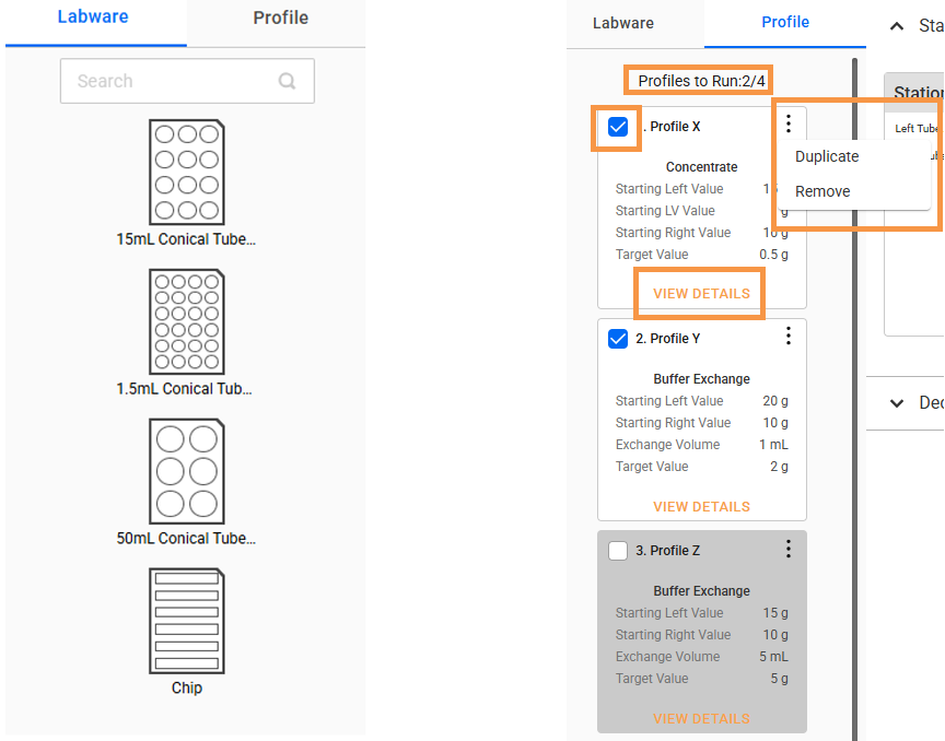
Labware Tab (Left); Profile Tab (Right)
Section 3: Station and Deck Panel
This section is a visual representation of the instrument’s station and deck. Expand the panel by clicking the arrow  or title to switch between displays.
Station: Click Edit
 on each station card to manually define the tube adapter. The cards below show 3 Concentration Stations (grey) and 2 Cleaning Stations (blue). If tube adapters are already installed, click Scan Adapter to automatically configure the Concentration Stations.
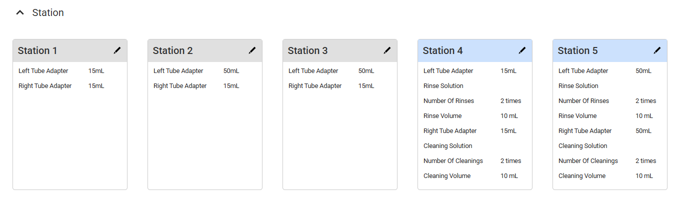
Station Card Panel
Deck: Drag and drop your desired racks from the Labware tab, then click the wells to specify your preferred tubes and chips.
Deck is Empty
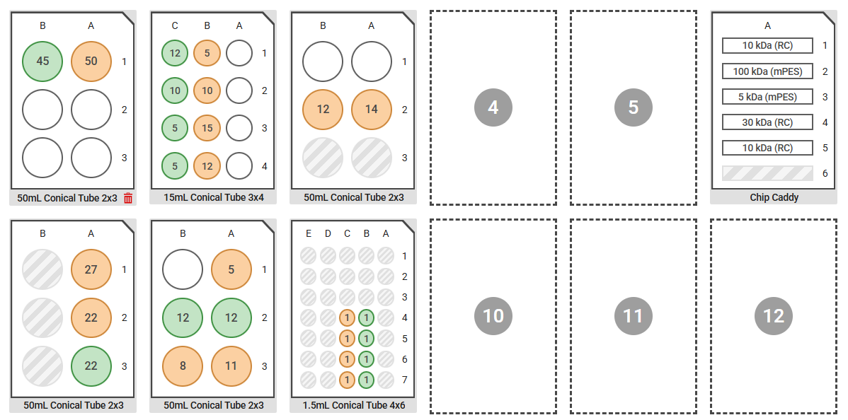
Defined Labware on Deck
To create a new protocol, see Creating a Protocol.
Runtime Status
The Runtime Status page provides real-time protocol progress and station activity. It opens automatically during a running protocol or can be accessed from the Status menu. This page includes a running profile list, active station statuses, and detailed process data in graphical format. See Runtime Status Page for details.
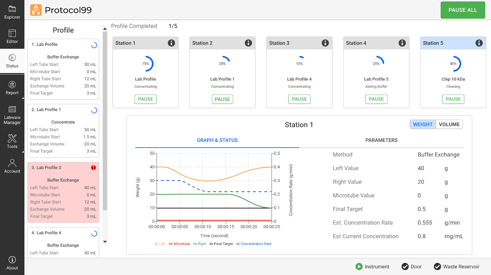
Runtime Status Page
Labware Manager
View available generic labware in the Labware Manager page. You can also calibrate and adjust the chip and labware definition to your experiment needs by clicking the EDIT button. This page is only accessible to Administrators.
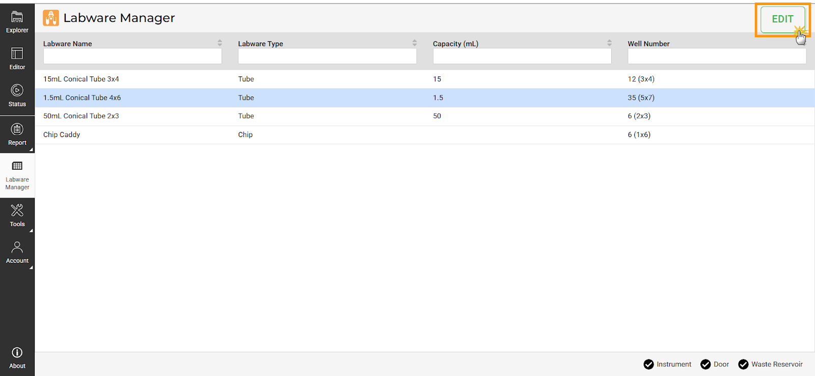
EDIT Button in Labware Manager
Tools
Switch between the pages below from the Tools menu to enhance system control and customization.
Calibration: Calibrate the scales to ensure accurate weight measurement.
Manual Control: Manually define the gantry and station configuration for testing or troubleshooting purposes.
Sequencer: Create profiles manually and execute custom sequences for specific protocols or tasks.
Performance Metric: Check the tubing lifespan on each peristaltic pump and identify any that need replacement.
Chip Cleaning: Clean batches of chips without the need for a fully defined protocol.
User Management
Admin-only function for registering and managing user accounts. For regular users, only the Account and Change Password menus are available to update your password and account info.
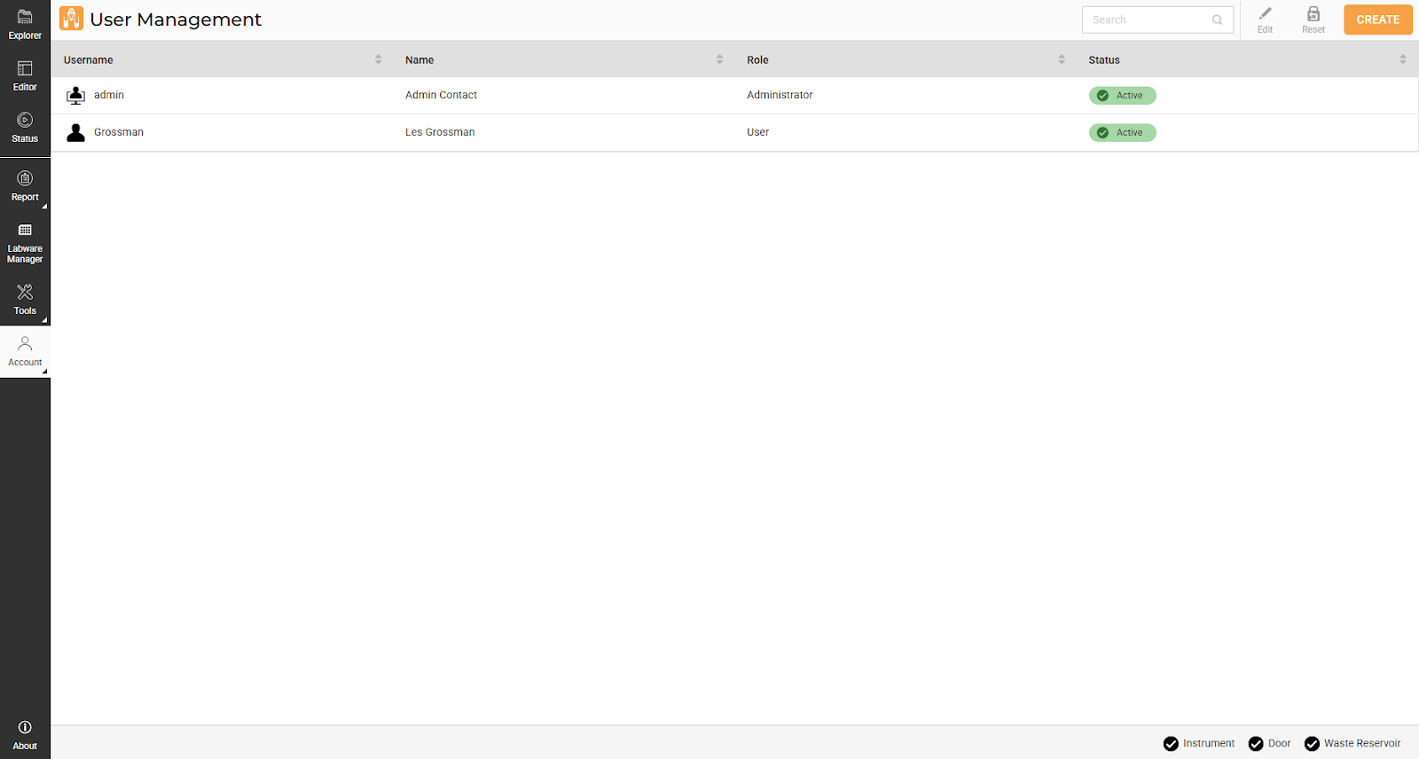
User Management Page
Setting Up the Instrument
Proper instrument setup is critical for ensuring the aµtoPULSE functions optimally. The steps below will guide you through setting up the instrument basics to ensure safety, efficiency, and cleanliness.
Setting Up The Reservoirs and Waste Container
Route the corresponding tubing according to the connections diagram and put the ends inside the buffer reservoir, cleaning reservoir, and waste container. The reservoirs must be adequately filled and maintained for continuous operation.
To help you monitor the liquid level in the waste container, aµtoPULSE provides a level sensor that warns you if it needs emptying. The sensor is detachable by simply pulling the velcro off its original location. Then, you can attach it to an empty container in the same orientation outside the container’s wall.
Note
Make sure that the sensor contacts the container wall securely to ensure accurate detection.
Preparing Cleaning Solution
The standard recommendation for cleaning is 0.1 M NaOH, but depending upon the application, different cleaning agents can be used. For example, if the only concern is sterility from bio-burden, the cleaning agent can be 10% NaClO or 3% H 2 O 2. For protein removal, 0.1 M NaOH or even detergents can be used. But for detergents, you need to be cautious and should perform a thorough rinsing afterwards. Other cleaning agents that can be used include:
0.1–0.5N NaOH
6M Guanidinium Hydrochloride
8M Urea
3% Hydrogen Peroxide
0.5% Sodium Hypochlorite
Setting Up the Station
Place the tube adapter on the station based on the profile configuration:
15 and 50 mL on the Right or Left scales
1.5 mL on the Microtube scale
Warning
Do not apply downward pressure when installing the adapter, as it may damage the load cell.
Setting Up the Deck
Here are some best practices to ensure optimal use of the deck area:
The Labware Rack Placement: Once the tubes are placed in the available nest on the deck, verify they are stable and aligned.
Place the chip rack close to the Concentration and Cleaning Stations. This reduces the risk of contamination from the chips to other tubes during transfers.
Regular Maintenance and Cleaning: Keep the deck surface clean and organized. Regularly inspect the area for spills or debris that could interfere with operations. A clean deck helps prevent contamination.
Calibrating the Scales
The scales in aµtoPULSE require periodic calibration to ensure accurate measurements. Perform calibration after initial installation, significant temperature changes, or noted volume inaccuracies. Follow the steps below to calibrate.
Prerequisites
Remove any tubes, tube adapters, and chips from the station.
No weight is applied to the scales.
Required Tools
100 g calibration weight
10 g calibration weight
To calibrate the scales:
In the aµtoPULSE software Navigation Bar, click Tools and select Calibration.
Navigate to the selected Station panel (for example, Station 1). Each station is calibrated individually and has three scales: Left Scale, Low Volume Scale (Microtube), and Right Scale.
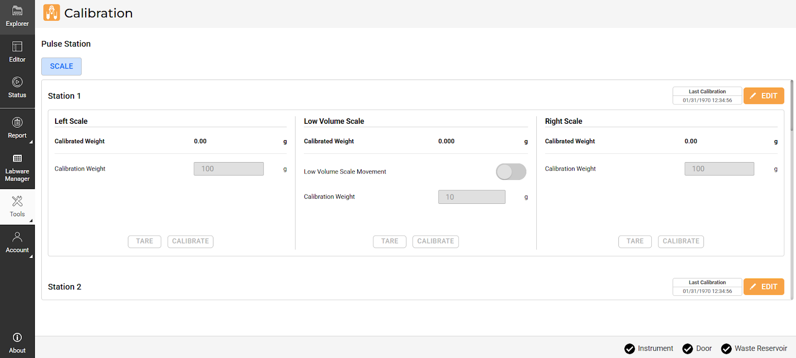
Calibration Page
Check the Last Calibration time displayed in the upper-right corner of the station’s panel. Click EDIT to start calibration.

Last Calibration Time
Do the following for each scale:
Left Scale and Right Scale
Click TARE to zero the scale.
Place the 100 g calibration weight at the center of the scale.
In the Calibration Weight field, enter 100.
Click CALIBRATE to initiate the calibration process. The Calibrated Weight should match the calibration weight entered.
Repeat steps a-d for the other scale.
Low Volume Scale (Microtube)
Important
The microtube scale is fragile; even slight contact can exceed its limit. Follow the steps carefully and avoid touching the scale to prevent damage.
Activate the Low Volume Scale Movement toggle to lift the scale.
Click TARE to zero the scale.
Turn off the Low Volume Scale Movement toggle to lower the scale.
Place the 10 g calibration weight at the center of the scale.
Activate the Low Volume Scale Movement toggle to lift the scale.
In the Calibration Weight field, enter 10.
Click CALIBRATE to initiate the calibration process. The Calibrated Weight should match the calibration weight entered.
Turn off the Low Volume Scale Movement toggle to lower the scale.
Click the SAVE button
 .
.Repeat steps 3-5 for the remaining stations.
Note
The Cleaning Station(s) do not have a Microtube Scale.
Creating a Protocol
Creating a protocol involves defining labware and creating profiles on the Editor page.
- Choose from the following options:
In the Explorer page, click Add Protocol, then OPEN. You can also double-click the Add Protocol button for quicker access.
Click the Editor menu (only after you log in).
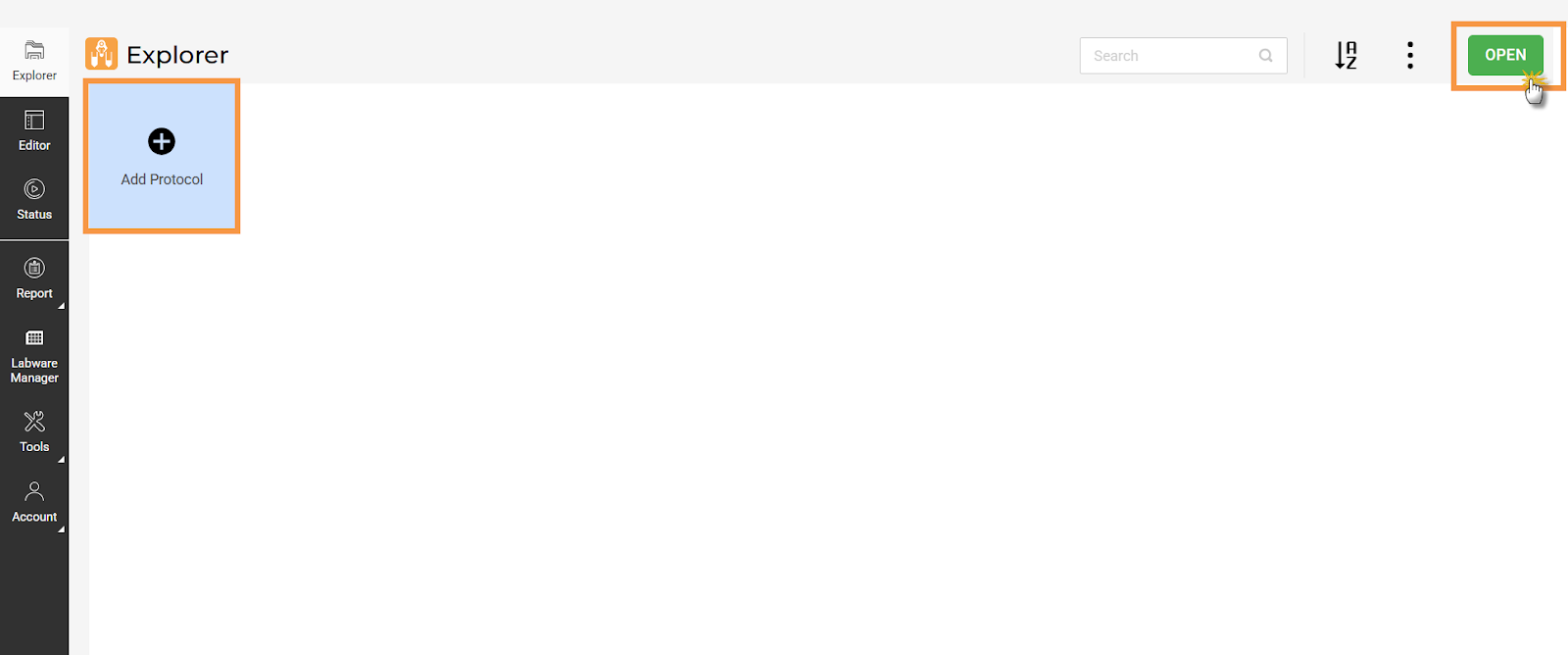
Click Add Protocol in the Explorer Page
OPTIONAL: On the Editor page, click the Import button
to load your predefined profile and labware data in a CSV file. Refer to the Importing Labware and Profile CSV topic for more information. Otherwise, you can manually define your protocol by continuing to step 3.
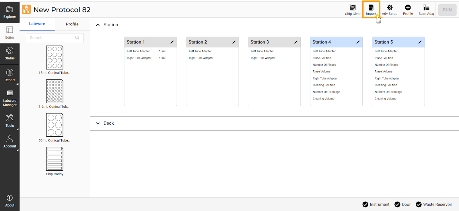
Click Import in the Editor Page
Define the labware and create profiles to include in the protocol.
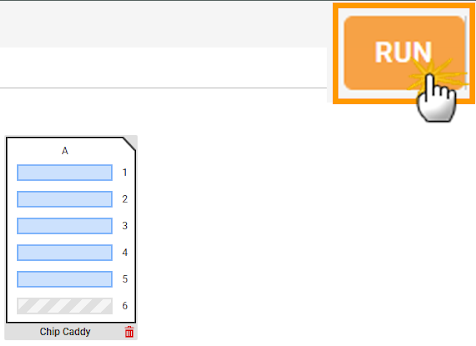
To execute the protocol, select the desired profiles, then click RUN.
_Selection_Before_a_Protocol_Run1.png)
Profile(s) Selection Before a Protocol Run
Chip Cleaning
Chip Cleaning enables you to clean batches of chips without the need for a fully defined protocol. Follow the steps below to configure or see details at Chip Cleaning.
- Choose from the following options:
Go to the Tools menu and select Chip Cleaning, then manually add the chip rack to the virtual deck.
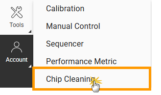
Chip Cleaning Option in the Tools Menu
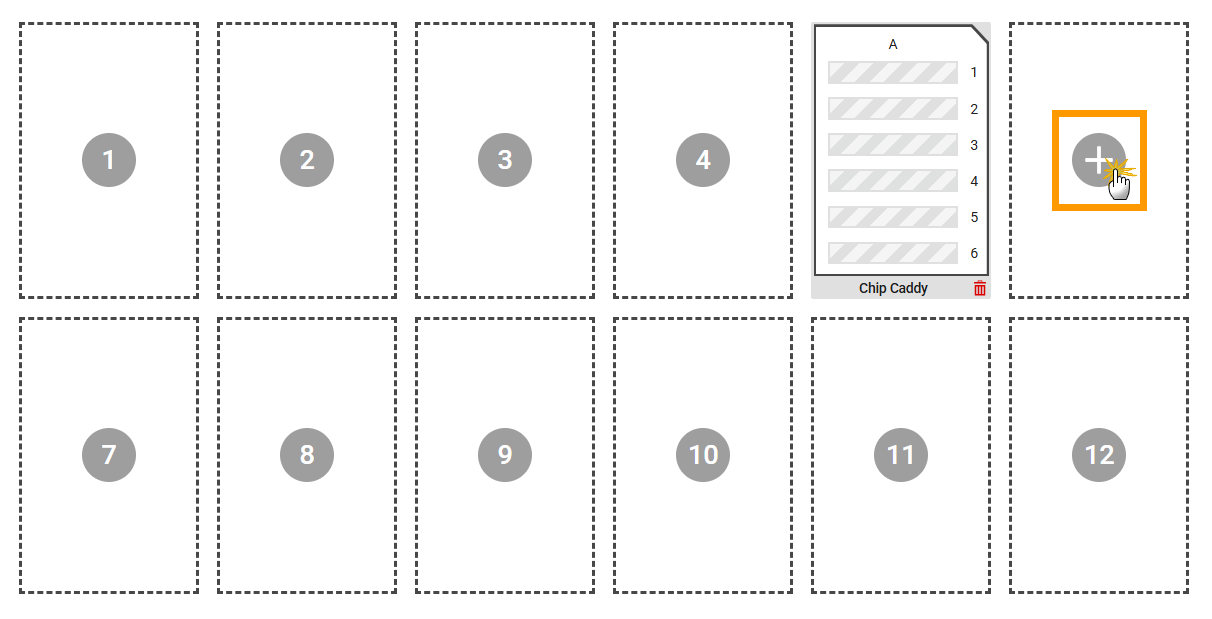
Add a Chip Rack to the Virtual Deck
Open a protocol and click Chip Cleaning. Then, click UPDATE to sync the chip selection based on the configuration from the Editor page.
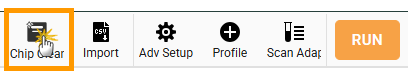
Chip Cleaning Button in Editor Page
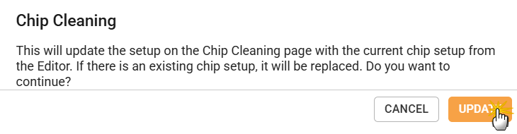
Chip Cleaning Setup Update Dialog
Select the chip you want to clean, then click RUN. Monitor the cleaning progress from the Runtime Status page.
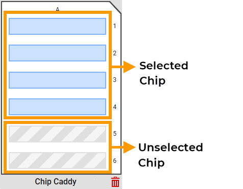
Chip Cleaning Selection
Click RUN in the Chip Cleaning page
Chip Storage
The aµtoPULSE Filtration Chips are rated for 300 mL of total permeate. Overuse of the chips can result in sample loss or damage to the device. For short-term reuse, chips must be stored wet in a sealed vessel. Long-term storage (>1 week) is not recommended unless a bactericide is added.
Note
It is highly recommended to run a chip-cleaning cycle before storage to remove residue, especially for crystallizing samples.
- Required Tools and Materials:
A sealable storage vessel
Water
- To store the chip:
Place the chip vertically in the storage vessel (transfer tubes facing up).
Fill the vessel with enough water to submerge the chip (excluding transfer tubes).
OPTIONAL: Seal and store the vessel in the refrigerator.
Label the stored chip with the total volume permeated. Note this volume for your chip’s lifetime records. Dispose of the chip if the total volume permeated exceeds 300 mL; functionality of the chip beyond this can not be guaranteed.
Chemical Compatibility
To ensure durability and optimal performance, consider the chemical compatibility of materials used in the device. Some chemicals are safe for continuous use, while others can cause damage and should be avoided. Certain substances may only be suitable for limited use and require additional testing. See Chemical Compatibility for detailed information.
Warning
The aµtoPULSE system and filter chips are not compatible with all chemical solutions. Use of solutions that are not recommended could damage samples, chips, or the aµtoPULSE instrument. Damage resulting from improper solution use may void the device warranty.