Peristaltic Tubing Harness Replacement Guide
This guide explains how to replace the external peristaltic tubing harness that connects the reservoirs and peristaltic pumps to the stations. Replacement is required if it becomes clogged, damaged, or reaches the end of its service life.
Note
This procedure is written for instruments configured for 3 Concentration Stations and 2 Cleaning Stations. If your instrument is configured for 4 Concentration Stations and 1 Cleaning Station, adjust the steps accordingly.
Required Part
Important
Before installing, inspect the new Peristaltic Tubing Harness Kit for any visible damage or defects.
aµtoPULSE Peristaltic Tubing Harness Kit (PN #: 848088B), includes:
Child Item |
Part Number (PN) |
Image |
QTY |
|---|---|---|---|
25 ft of Extension Tubing |
852202A |
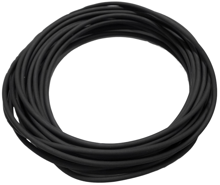
|
1 pc |
Dispensing needle |
826301A |
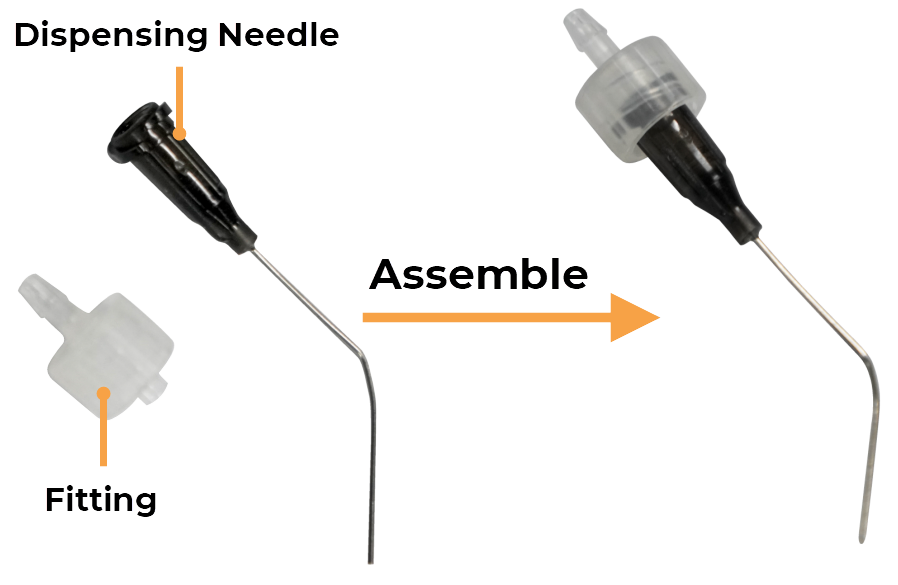
|
10 pcs |
Fitting |
817309A |
||
Internal Device Peristaltic Tubing Harness Assembly |
838105B |
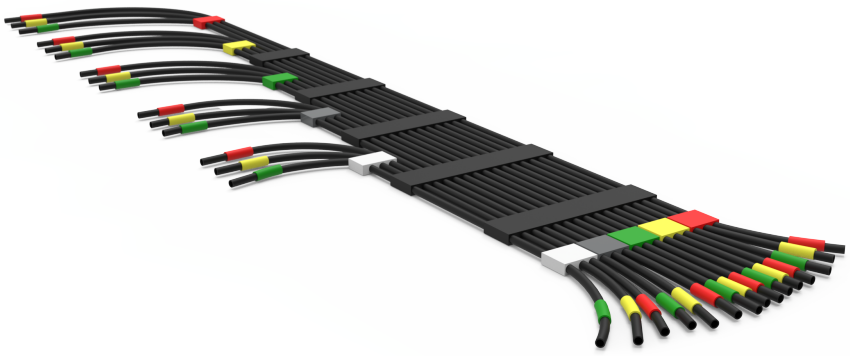
|
1 pc |
Peristaltic Pump Tubing |
817792A |
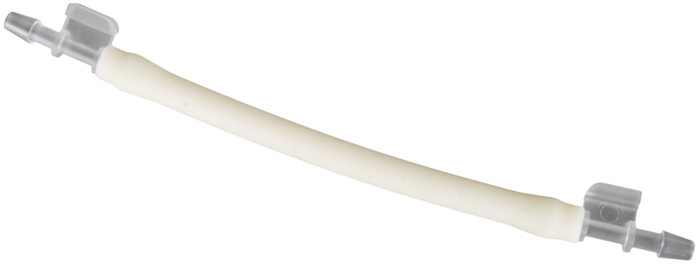
|
9 pcs |
Required Tools
Tubing cutter (to cut the extension tubing)
Nitrile gloves (optional, for hygiene and safety)
Flashlight (optional, for better visibility of tubing connections)
Section 1: Preparation
Insert the ends of red and green-tagged tubes into the waste container to collect the liquid from the retraction process.
Retract the pump to drain remaining liquid from the tubing:
Open the Manual Control page from the Tools menu.
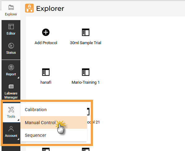
Select Manual Control
Select STATION #, then expand the Pulse Station Movement tab.
Under Retract External Buffer Pump, set the retraction time for 30 seconds to remove any remaining liquid from the station, then click Run
 .
.Tip
Ensure the tubing is dry by checking that only air bubbles are dispensed into the waste container. If liquid remains, rerun the Retract External Buffer Pump or increase the retract duration.
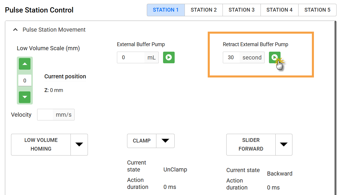
Retract External Buffer Pump on Concentration Station
Important
Before running a retraction on a Cleaning Station, set Drain Waste to OFF before switching to the next station.
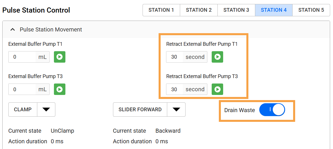
Retract External Buffer Pump on Cleaning Station
Repeat steps b–c to retract the liquid on other stations.
Power off the instrument and pump box before moving on.
Clear the deck and stations of all adapters, labware, and racks. Remove the waste container and buffer reservoirs.
Measure and cut the 25 ft tubing as needed based on the pump and reservoir position. See Section 3 for detailed instructions.
Tip
Use the removed Peristaltic Pump Tubing as a measurement guide for the replacement tubing.
Section 2: Removing the Peristaltic Tubing Harness
Note
Retain the tubing in the Waste Drain pumps and cleaning station, as it doesn’t need replacement.
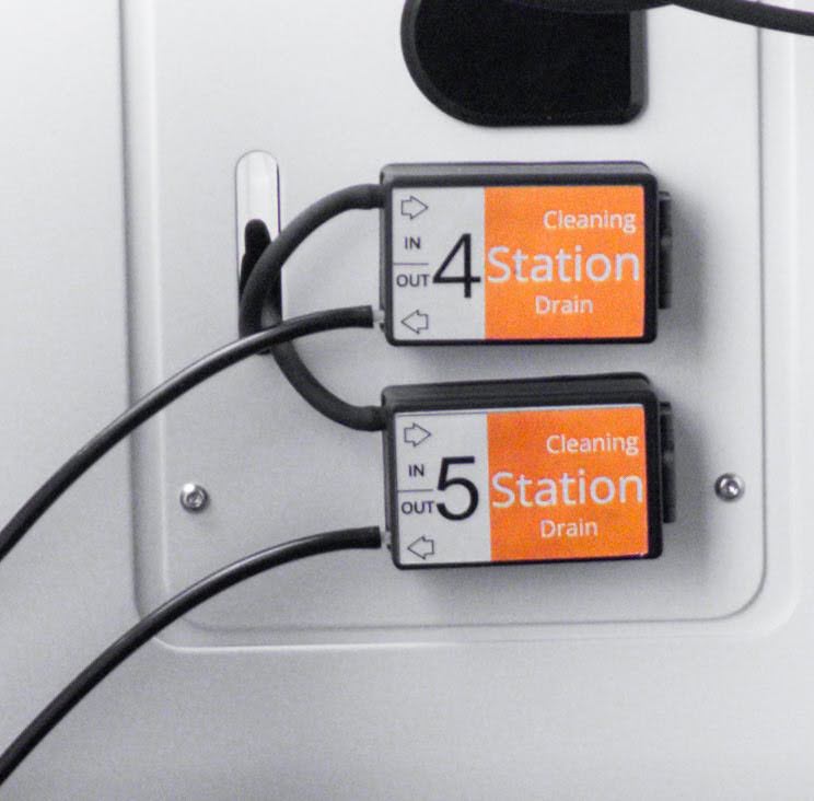
Waste Drain Tubing
Waste Tubing in Cleaning Station
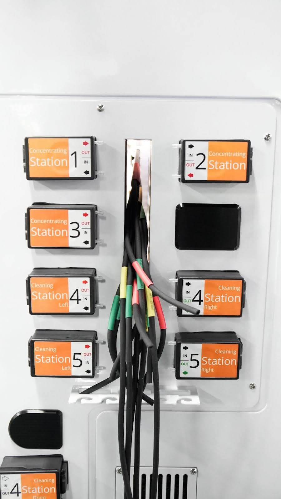
At the Peristaltic Pump Panel:
Tip
For quicker tubing removal, open the pump door completely and remove the entire tubing while still connected. Then, proceed to step 2.
Tubing Set in the Peristaltic Pump
Carefully disconnect tubing from the IN and OUT ports on the Concentration and Cleaning pumps.
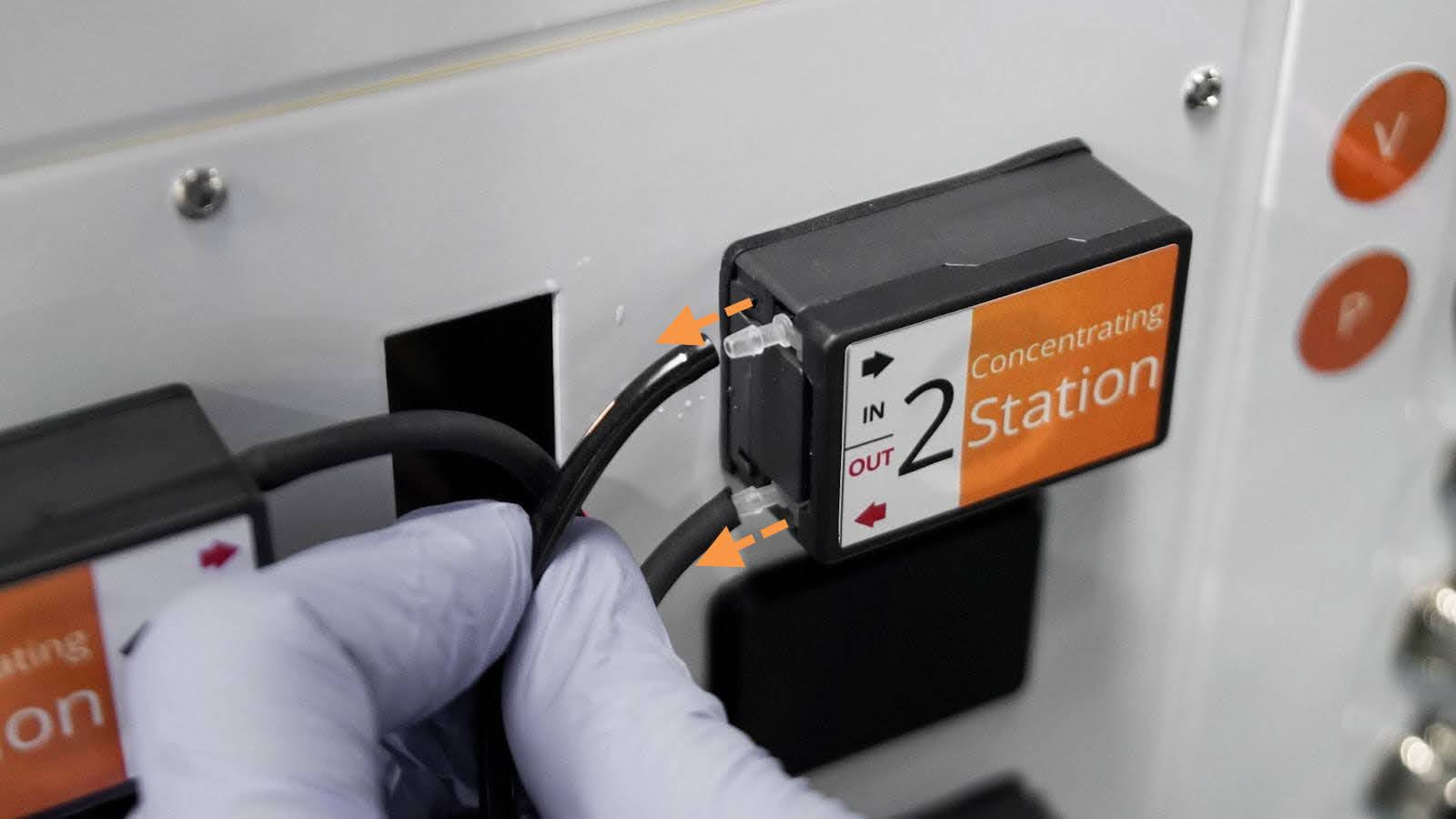
Pulling the Tubing Out
All Tubings Disconnected
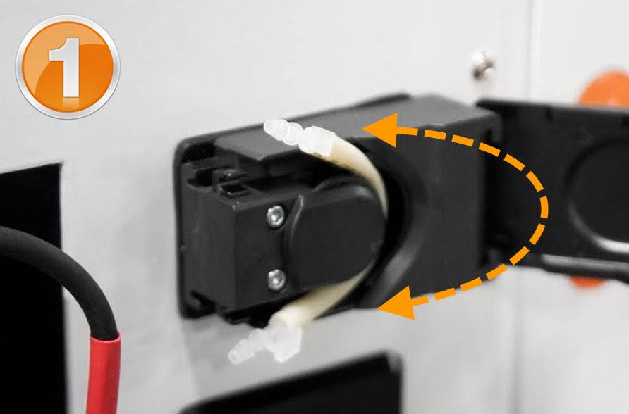
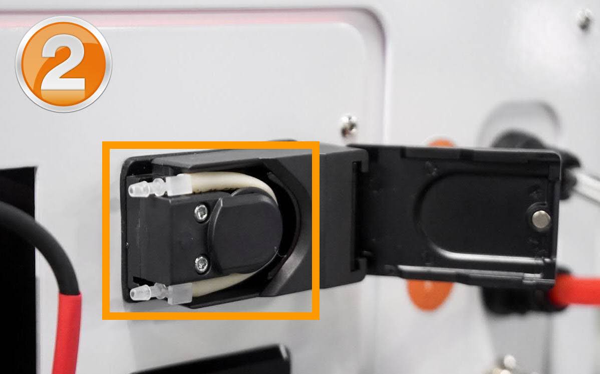
Remove the tubing inside each pump:
i. Open the peristaltic pump door completely.
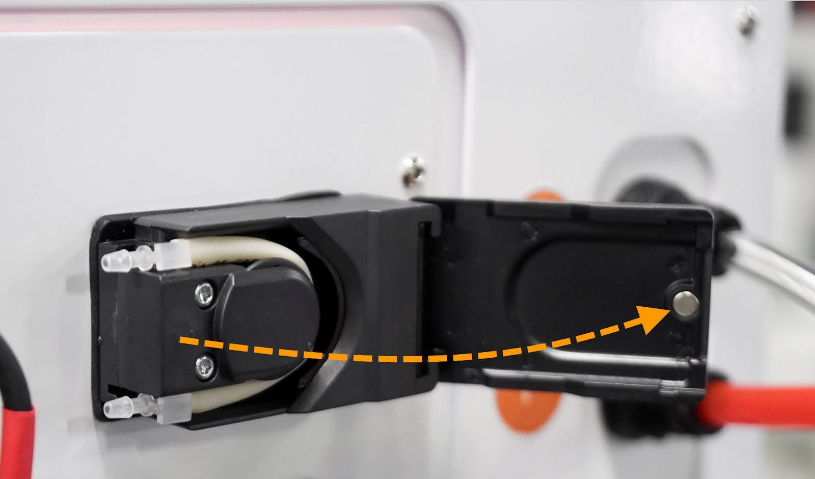
Opening The Peristaltic Pump Access Door
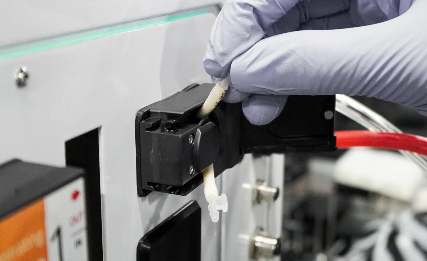
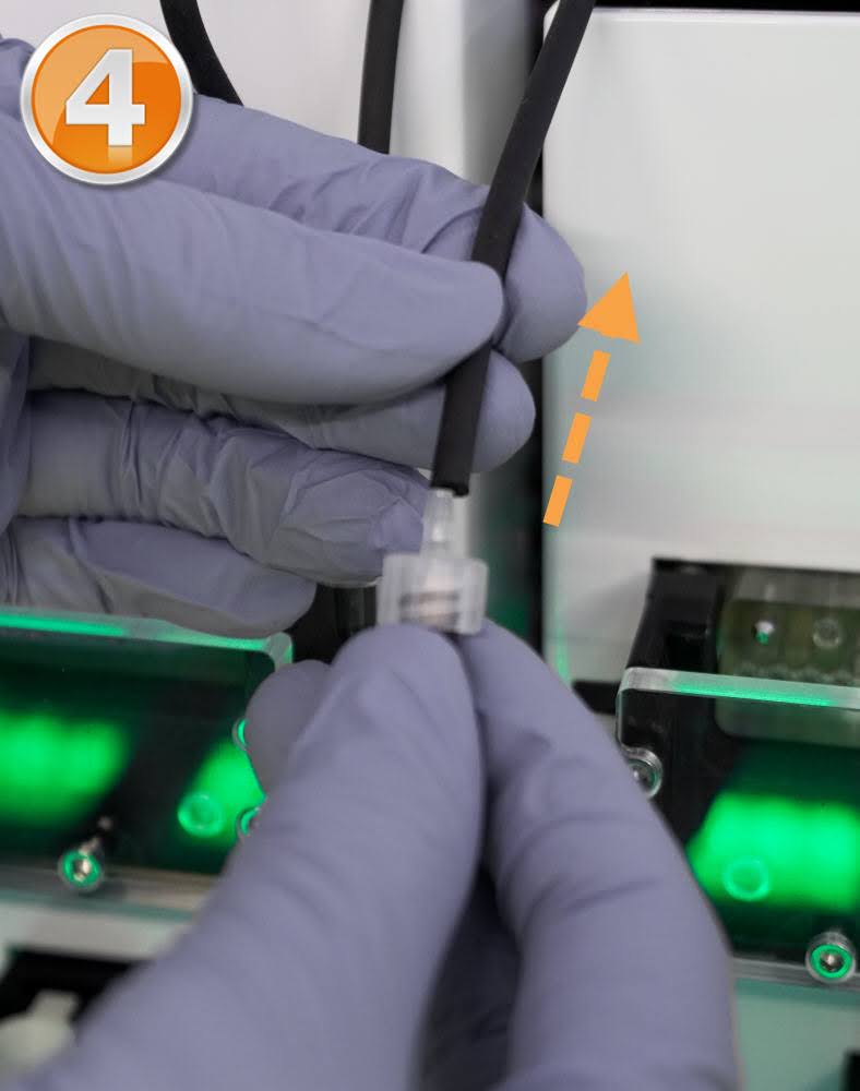
ii. Pull the tube connector out of the fitting.
Pull Out The Tube Connector
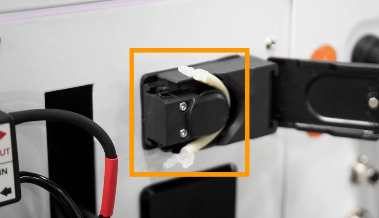
Tube Connector Out
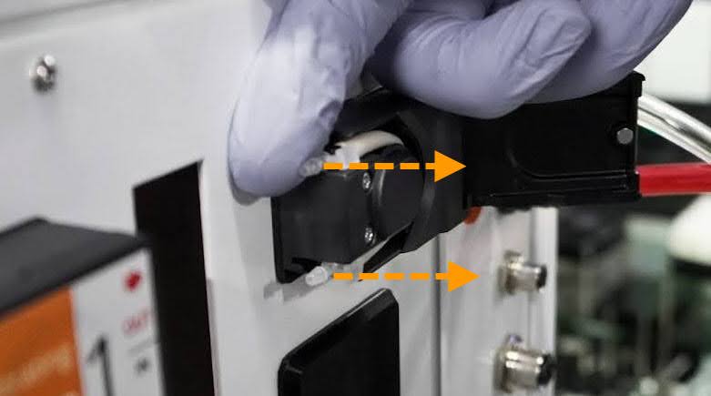
iii. Carefully remove the pump tubing from the housing, then close the pump door.
Removing The Pump Tubing
Disconnect the tubings accordingly from Stations 1 to 5 as follows:
Remove the waste tubing from the Permeate Port.
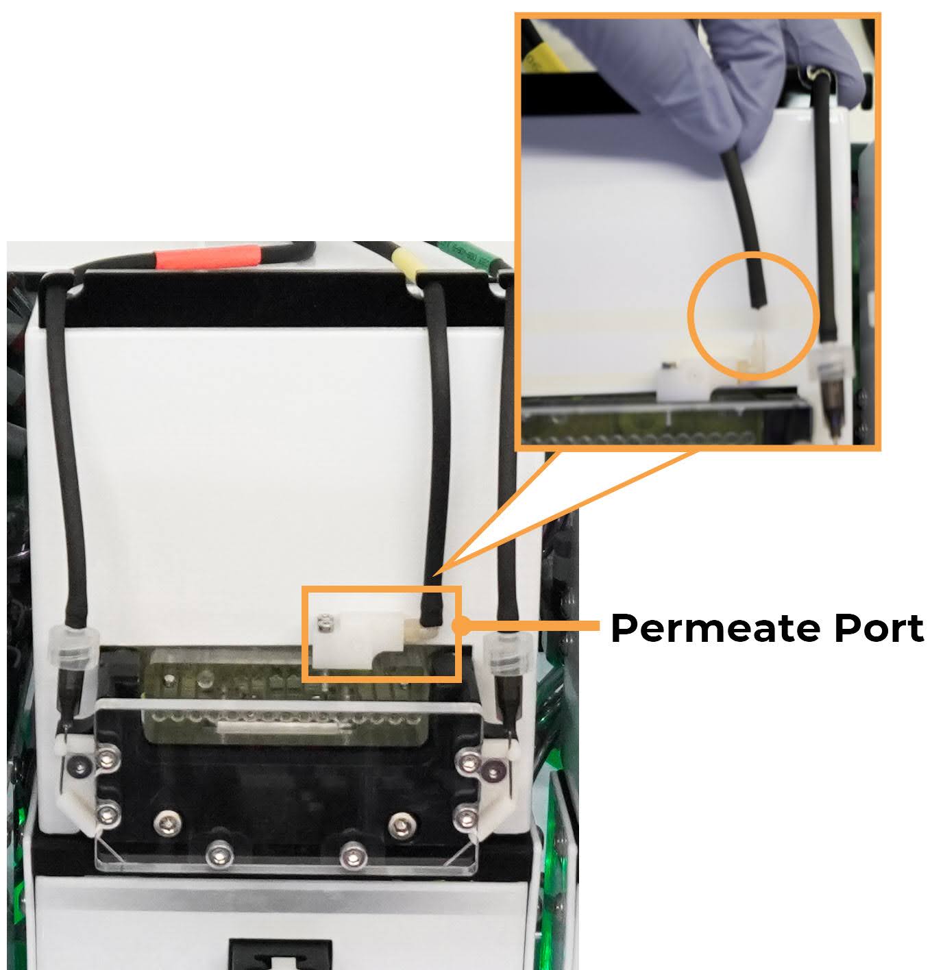
Pulling Off the Waste Tubing
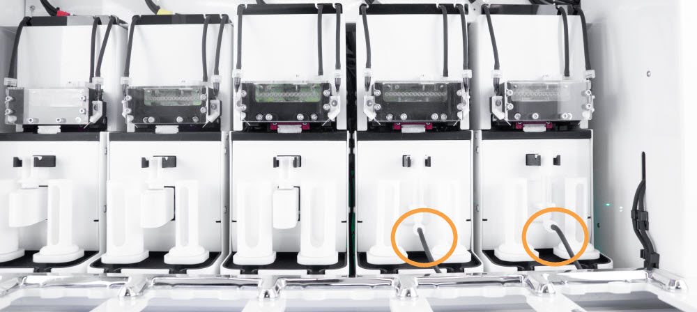
Remove the transfer needle from each station’s right and left sides:
Note
The transfer needles are secured with light tension similar to a standard safety pin.
Warning
The needle is thin and sharp. Handle carefully to avoid injury or bending.
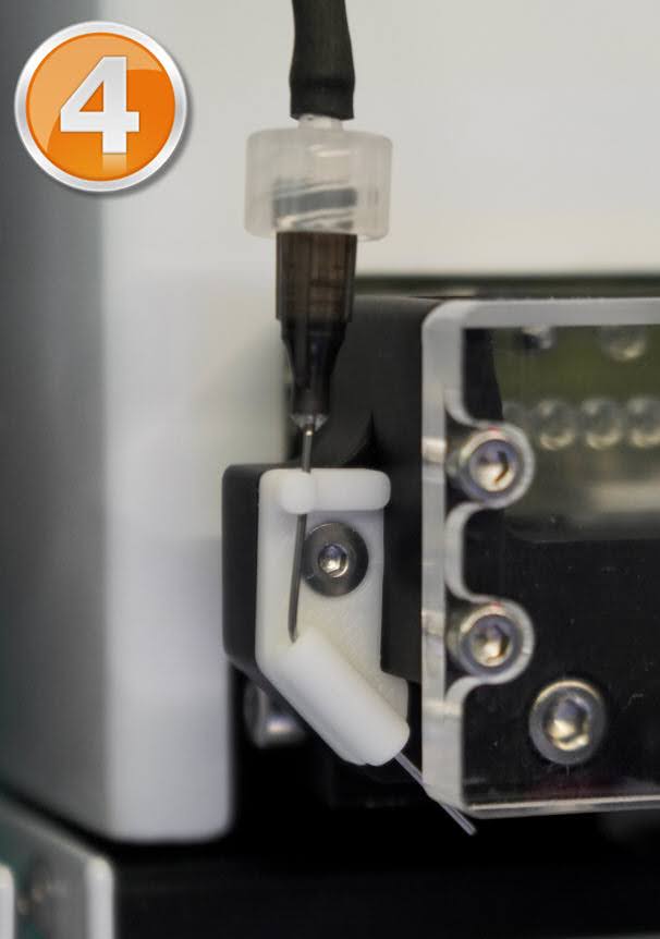
i. Detach the needle from the upper holder.
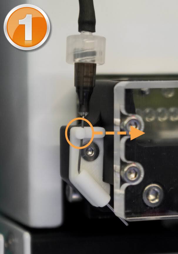
Needle Detachment from the Upper Holder
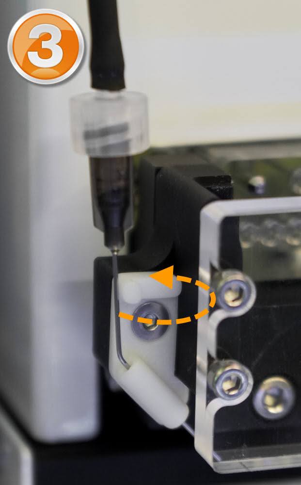
ii. Carefully move the needle to the side as shown below.
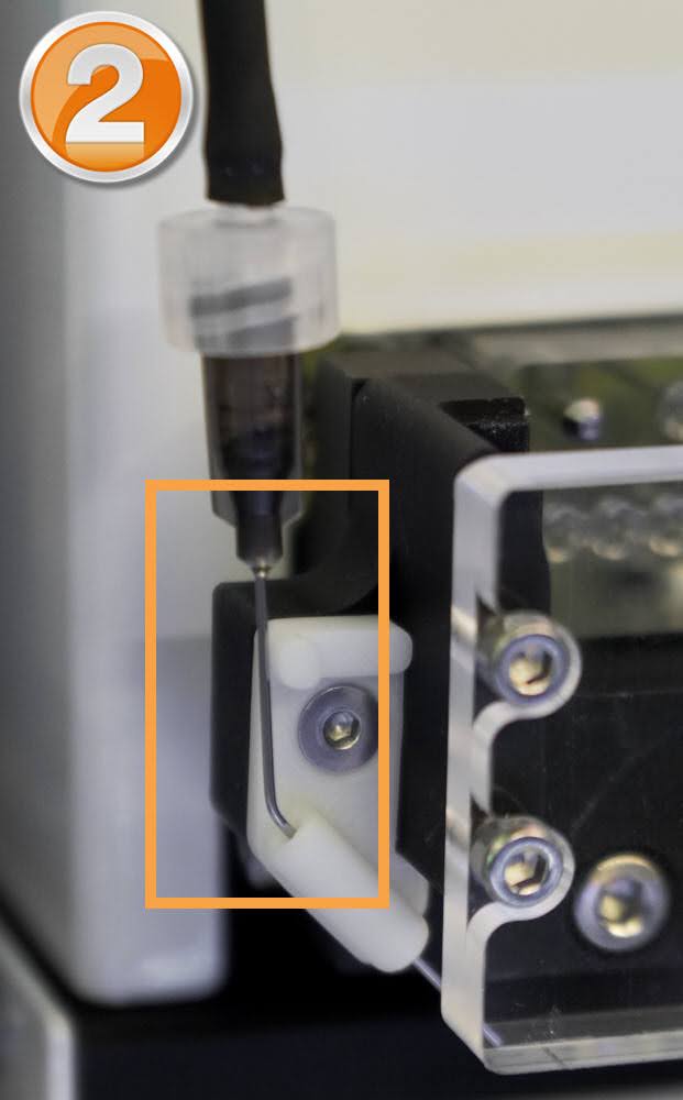
Carefully Move the Needle to the Side
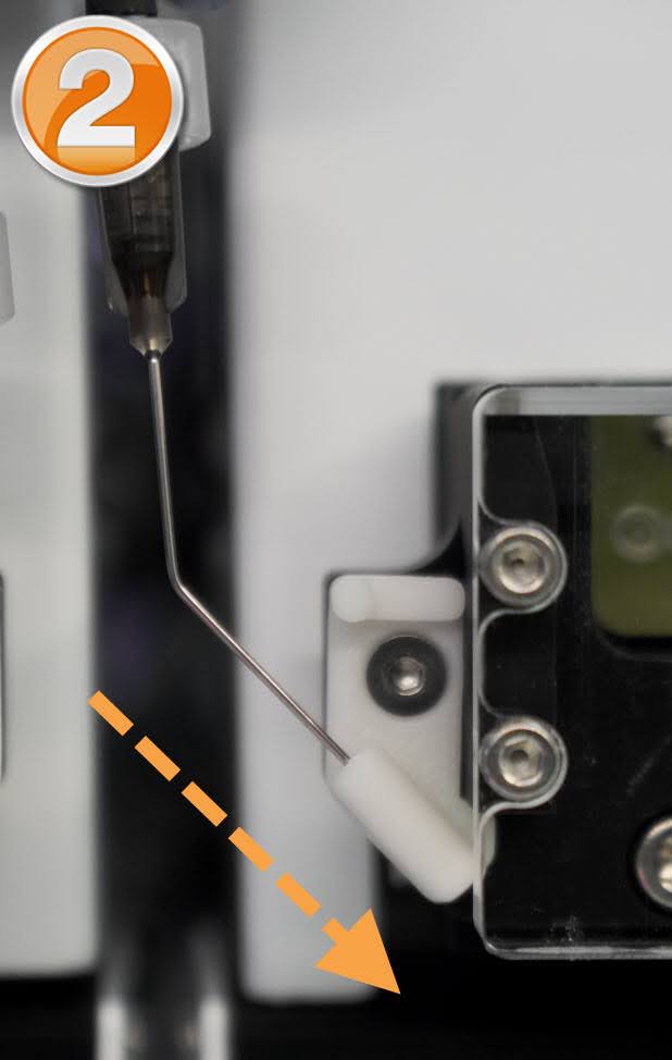
iii. Gently pull upward to remove the needle from the holder.
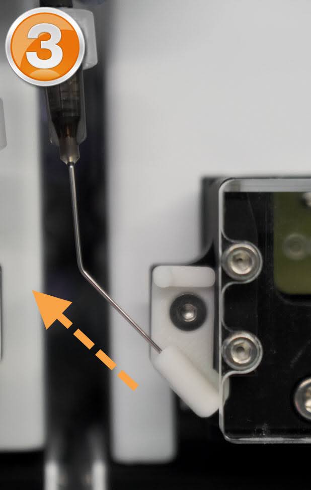
Pull Upward to Remove the Needle from the Holder
iv. Disconnect the transfer needle from the tubing.
Disconnect the Transfer Needle from the Tubing
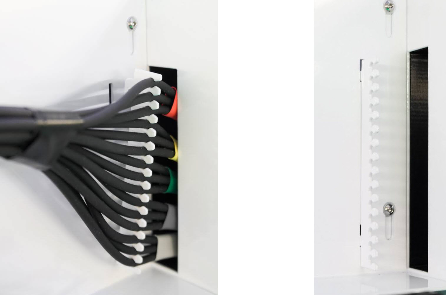
Remove the tubing set from the slots and path as shown below.
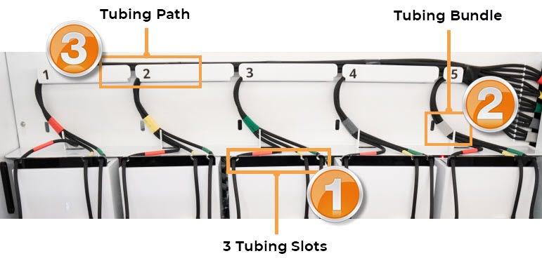
Tubing Slot and Path
Removing the Tubing Set
Remove the tubing set from the tube clip, then pull the remaining tubing out through the hole on the right side.
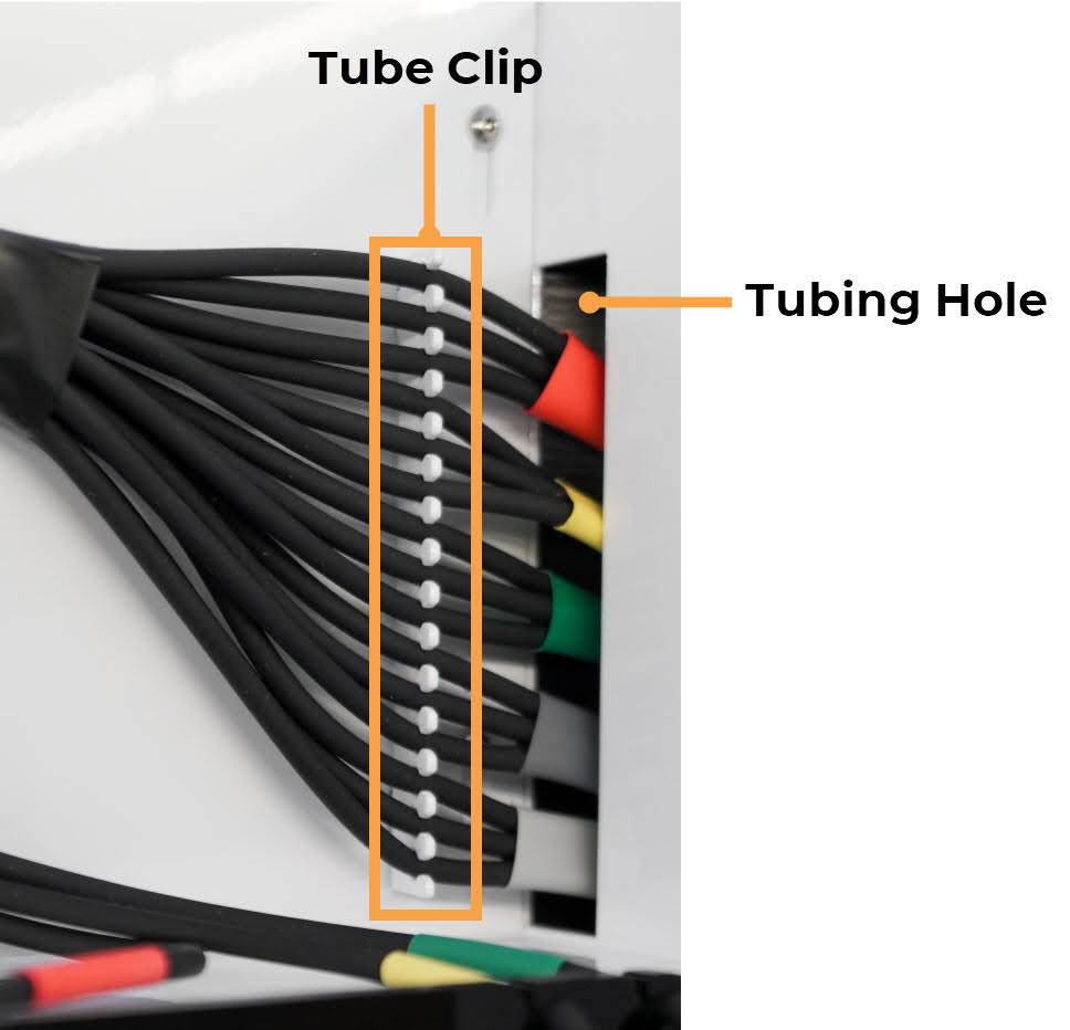
Removing Tubing from Tube Clip and Hole
Tip
For easier removal, detach the tube clip from the tubing set. Then, re-attach the clip afterward.
Detaching the Tube Clip with Tubing (Left); Tube Clip is Re-attached (Right)
Section 3: Installing the New Peristaltic Tubing Harness
Insert each color-tagged tubing into the tube clip and pass the ends through the tubing hole. Refer to the image below for correct placement (Station 1–5).
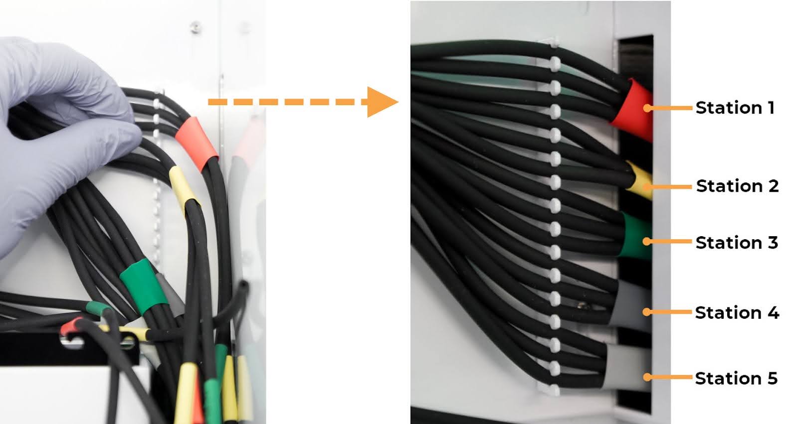
Inserting the Tubing into the Tube Clip
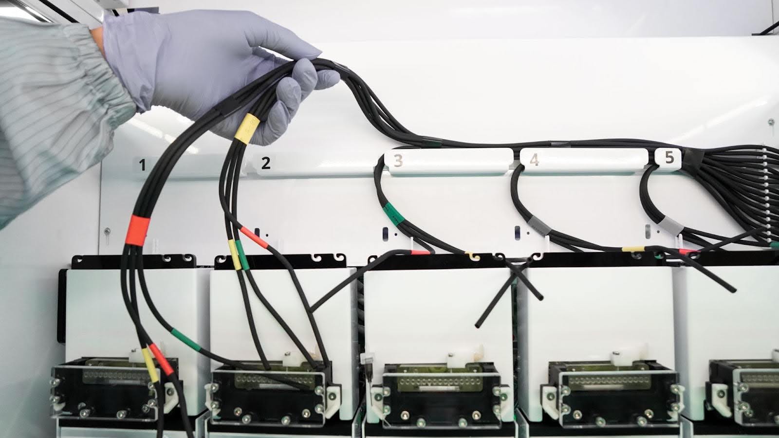
Install the tubing at the stations:
Important
Position the tubing properly to keep it clear of the gantry and prevent damage.
Guide the tubing through the tubing path.
Insert each bundle into the holder according to the color tags on the corresponding station.
Route each color-tagged end into the guides and their corresponding parts.
Red: Buffer outlet (Left)
Yellow: Permeate Port
Green: Cleaning solution outlet (Right)
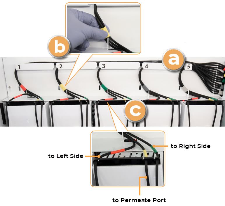
Inserting Tubing into the Corresponding Slots
Install the transfer needle on the Right and Left sides of the station. Refer to the images below.
a. Connect the tubing to the needle’s fitting.
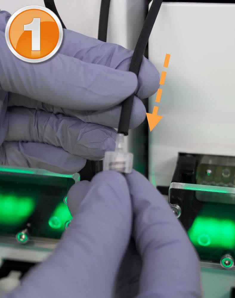
Connect the Tubing to the Needle Fitting
b. Insert the needle until the angled section rests above the slot.
Needle Insertion Position Above the Slot
c. Move the needle over and insert it into the slot.
Insert the Needle into the Slot
d. The proper needle placement:
Proper Needle Placement
Insert the Yellow-tagged tubing into the Permeate Port.
Installing the Waste Tubing
Install the tubing in each peristaltic pump:
a. Open the pump door, insert the new tubing into the housing until it is securely seated.
Installing The Pump Tubing
b. Verify that the pump tubing is fully inserted and the tube connectors are secured in the fittings, then close the pump door.
Properly Installed Pump Tubing
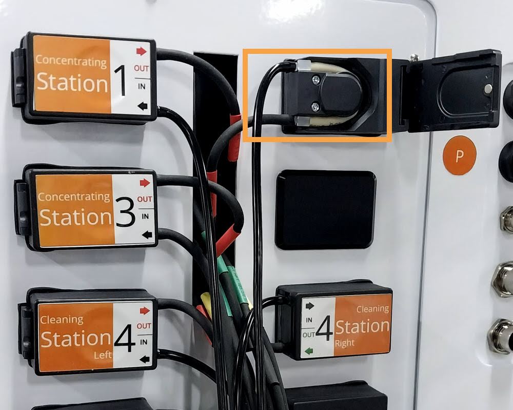
Connect the tubing to each corresponding port as follows.
Important
Verify all tubings are routed through the hole and connected to the correct pumps according to color tags. Incorrect connections may cause liquids to be pumped into the wrong outlet. Use a flashlight if needed for better visibility.
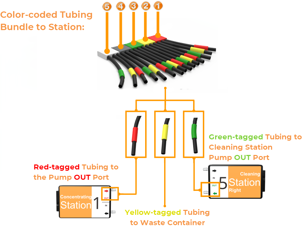
Color-coded Tubing Connections
Route the Yellow-tagged tubing into the waste container.
Plug the red and green-tagged tubing into the OUT port of the corresponding pump.
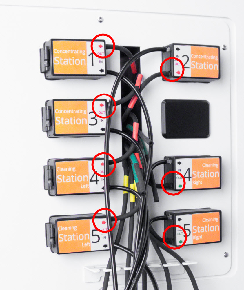
Plug the Tubing into OUT Ports
Plug the extension tubing into each corresponding IN port.
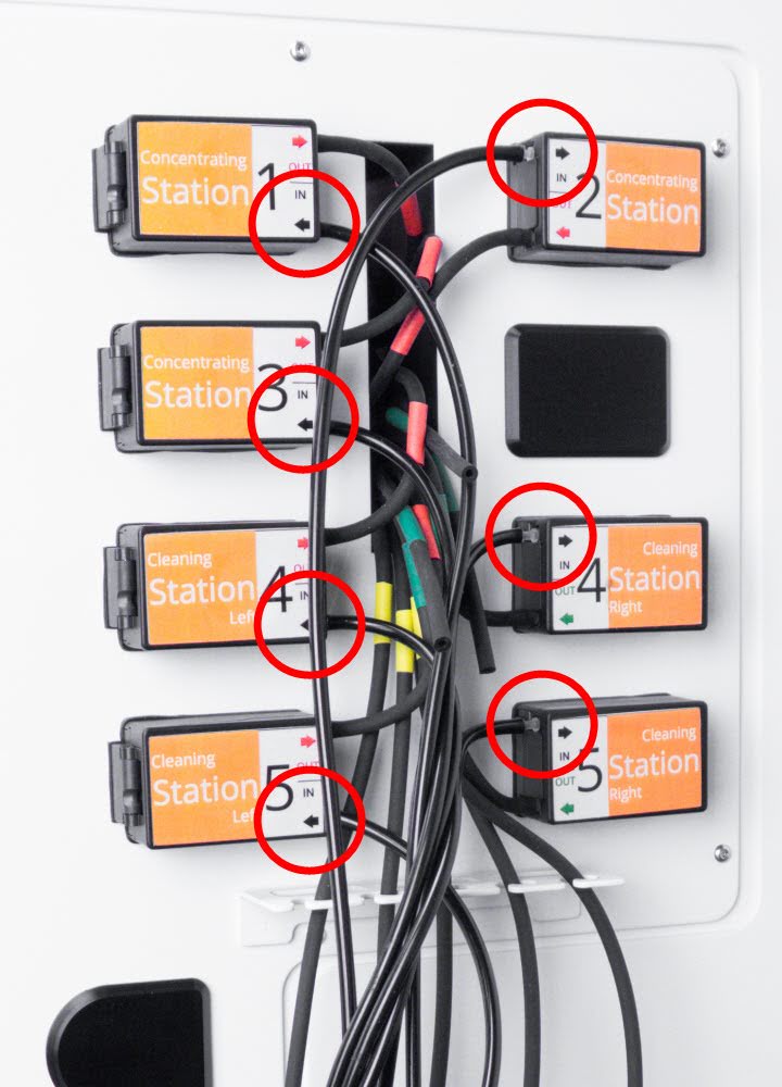
Plug the Extension Tubing into IN Ports
Verify all tubings are properly connected and secure to prevent leaking.
Section 4: Testing the Installation
Reinstall the waste container and buffer reservoirs.
Place the tube and tube adapter on the stations.
Reconnect the power cable and turn on the instrument. Ensure the door is closed and wait for initialization to complete.
Open the software and go to the Manual Control page.
Select STATION # and expand the Pulse Station Movement tab.Then, define the following parameters:
Select SLIDER FORWARD to move the station forward and prevent liquid from entering the gap between the station’s top and bottom sections.
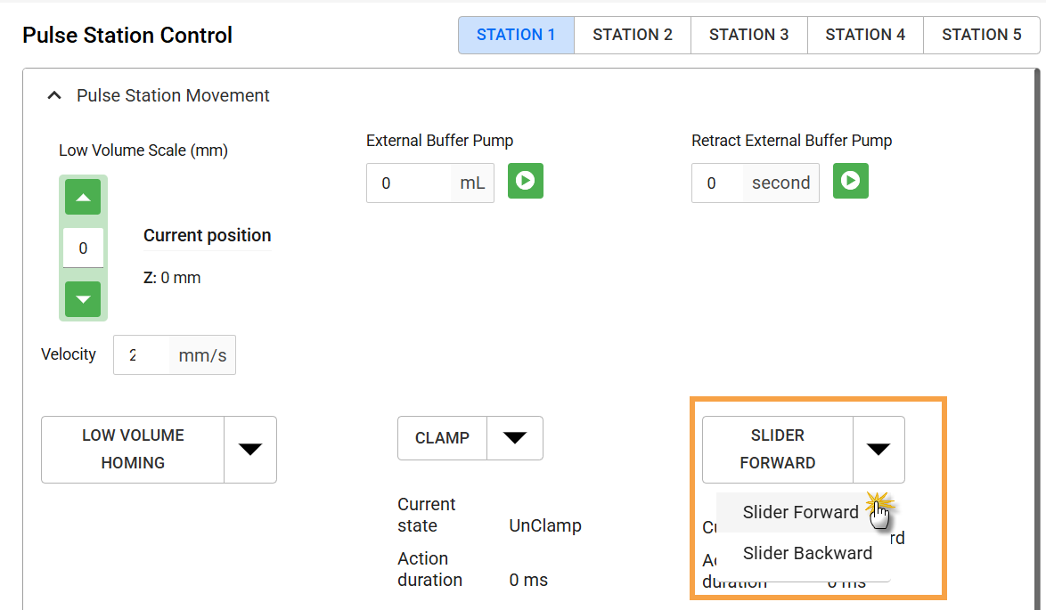
Click SLIDER FORWARD
Enter 5 mL and run the External Buffer Pump (you can use either buffer or cleaning solution). If the pump can stop automatically once reaching 5 mL at the station, testing is successful.
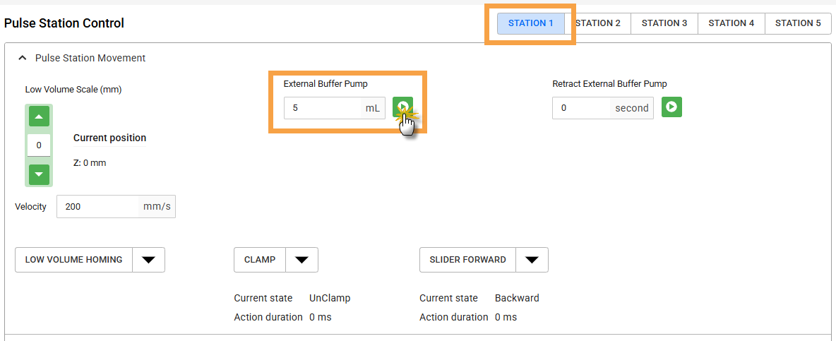
Pumping 5 mL of Liquid on Concentration Station
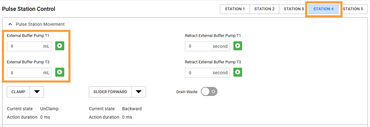
Pumping 5 mL of Liquid on Cleaning Station
If a timeout error occurs during circulation, repeat steps 5a-b until it clears. If gurgling or no liquid flows during testing, open and close the pump door or gently push the tubing deeper into the housing.
Inspect all tubing and connections for leaks or mismatched destinations. Liquid should flow only from the correct station’s buffer and/or cleaning outlets, with no leaks along the tubing.
Repeat steps 5-7 for the connections on the remaining stations.