Mold Design
Mold design refers to a digital design of a mold. As the initial phase in the Injection Mold Engineering (IME) system, it ensures that the requested design has been carefully assessed before the CNC operators create the mold.

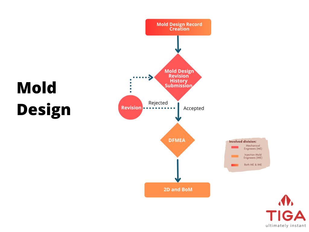
Mold Design Flow Chart
The mold design process starts when the mechanical engineer (ME) creates a record in the Mold Design table with the help of the mold engineers. Once created, ME attaches 2D/3D drawings to the Attachment table and specifies the mold design’s verifier and approvers in the Mold Design Revision History table. Upon submission, TIGA will keep all stakeholders updated by sending notification emails. Once the record is Approved, the mold engineers will continue the mold design process by preparing the mold design’s failure mode and effect analysis (DFMEA), 2D, and bill of material (BoM).
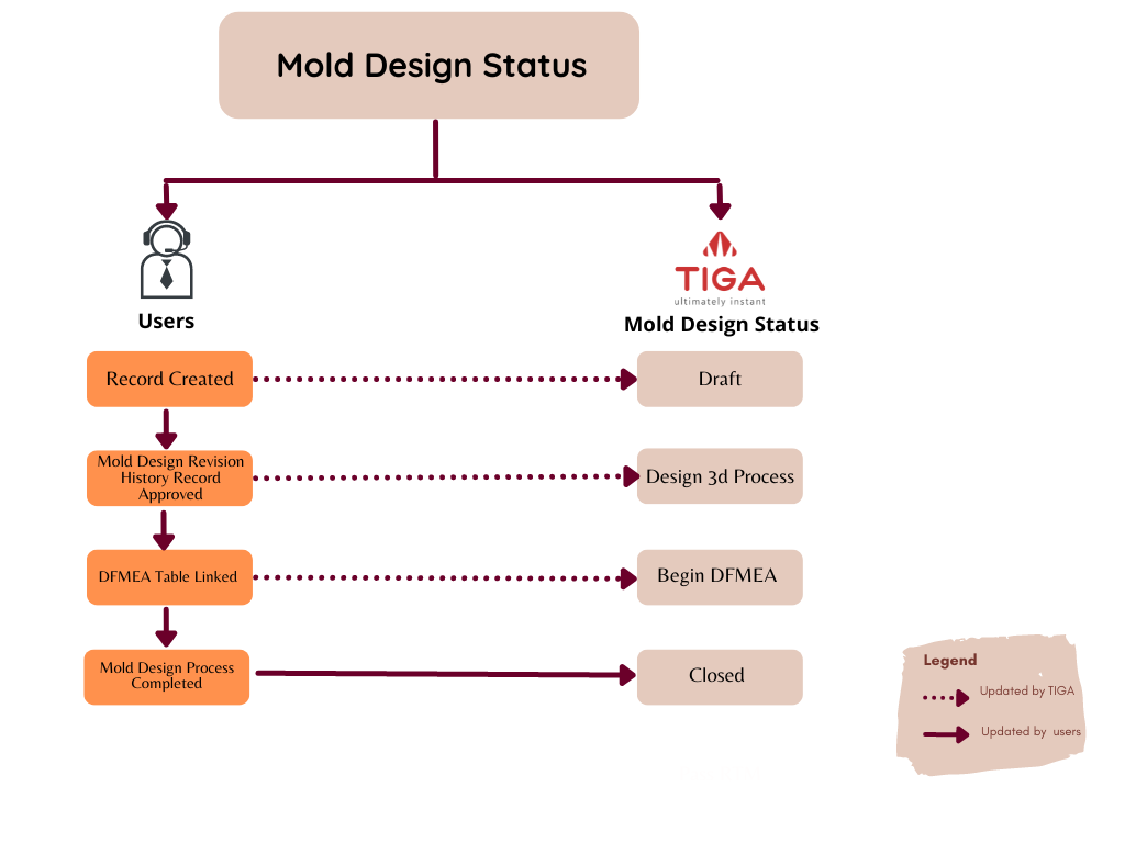
Please check the Status column to monitor the progress of the mold design.

Mold Design Status
Status Name |
Description |
|---|---|
Open |
It is the status of a newly created record. |
Design 3D Process |
The Mold Design Revision History status is Approved, meaning all approvers approve the submitted record. |
Begin DFMEA |
The mold engineers link the Design Molding Revision History to the DFMEA table. |
Closed |
The mold engineers manually update the Mold Design record status when the mold design process finishes. |
Creating a Mold Design
To create a mold design request:
Create a new record in the Mold Design table.
Complete the mandatory fields (shown by *) in the Mold Design Request/FRM-14-001-007 and Product Specification/FRM-14-001-006 sections.
Upon the request creation, TIGA will send a notification email to the Formulatrix project’s mailing list and update the record status to Open.

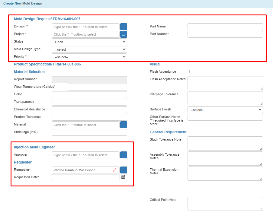
Create New Mold Design Window
Below are the fields in the Create New Mold Design window and their descriptions.
Mold Design Request/FRM-14-001-007
Field Name |
Description |
|---|---|
Division* |
Requester’s Name and Formulatrax ID. |
Project* |
Product type. |
Status |
A field to define the record’s status. If you leave it empty, it will be set to Open. |
Mold Design Type |
Mold design purpose (Engineering or Production). Choosing Engineering requires you to complete either the Part Name or Part Number fields, while choosing Production requires you to complete both. |
Priority* |
Mold design urgency (Medium, Urgent, or Top Urgent). |
Part Name |
Requested part’s name filled by the requester. Consult the project’s PIC. |
Part Number |
Requested part’s number filled by the requester. Consult the project’s PIC. |
Product Specification/FRM-14-001-006
Material Selection
Field Name |
Description |
|---|---|
Wear Temperature (Celcius) |
Maximum temperature the material (plastic) can handle. Note The value will affect the material used to create the part, i.e., PP, ABS, etc. |
Color |
Part’s color as approved by the PM in FUSA. |
Transparency |
Transparency indicator. Select Yes if the part is transparent or No if it is not. |
Chemical Resistance |
List of chemicals harmful to the materials. |
Product Tolerance |
Expected dimensional variations (µ) of the product due to factors like temperature, machine, materials, etc. |
Material |
Type of engineering material, for example: acrylic, silicon, PFE, and others. |
Shrinkage (in%) |
Percentage of material compression/shrinkage listed in the material safety data sheet. |
Injection Mold Engineer
Field Name |
Description |
|---|---|
Approver |
IME Division Manager’s name. |
Requester
Field Name |
Description |
|---|---|
Requester* |
Requester’s name. |
Requester Date* |
Record creation date. |
Visual
Field Name |
Description |
|---|---|
Flash Acceptance |
Excess materials indicator. Check if excess materials exist. |
Flash Acceptance Notes |
Value (µ), characteristics, and Flash Acceptance position. |
Warpage Tolerance |
The maximum value (µ) of acceptable material bending. |
Surface Finish |
Surface texture types including Glossy, Texture, Mirror, Sand Blast, and Other. |
Other Surface Notes **)required if surface is other |
Additional information if selecting Other in the Surface Finish. |
General Requirement
Field Name |
Description |
|---|---|
Stack Tolerance Note |
Tolerance value (µ) of the item’s mechanical fit with other parts/components. |
Assembly Tolerance Note |
Tolerance value (µ) of the precision position between parts/components. |
Thermal Expansion Notes |
Acceptable value (µ) of matter changes because of the thermal. |
Critical Point Note |
Important information about the part quality. |
Creating Mold Design Revision History
After adding attachments, create a record in the Mold Design Revision History table, and specify the verifier and approvers. ME only needs to complete the Attached Data section as TIGA automatically fetches the data in the FRM-14-001-007 section from the Mold Design table. The following are fields in the Attached Data section and their descriptions.
Field Name |
Description |
|---|---|
Attached Data |
Type of attachment. |
Finished Date Plan |
Expected finish date of the mold design request. |
Verified By |
Project leader. |
Approver 1 |
ME manager. |
Approver 2 |
IME manager. |
Approver 3 |
FUSA product manager. |
Note
When the record is created, TIGA will set the Mold Design Revision History record to Draft.
Submitting Mold Design Revision History
Mold engineer reviews the Mold Design Request and Product Specification sections in the Mold Design table before submitting the Mold Design Revision History record.
Tip
Read editing records to add product specifications.
To submit mold design revision history:
Select a mold design record in the Mold Design table.
Open the Mold Design Revision History table on the Related Tables.
Note
Only a Draft Mold Design Revision History record can be submitted.
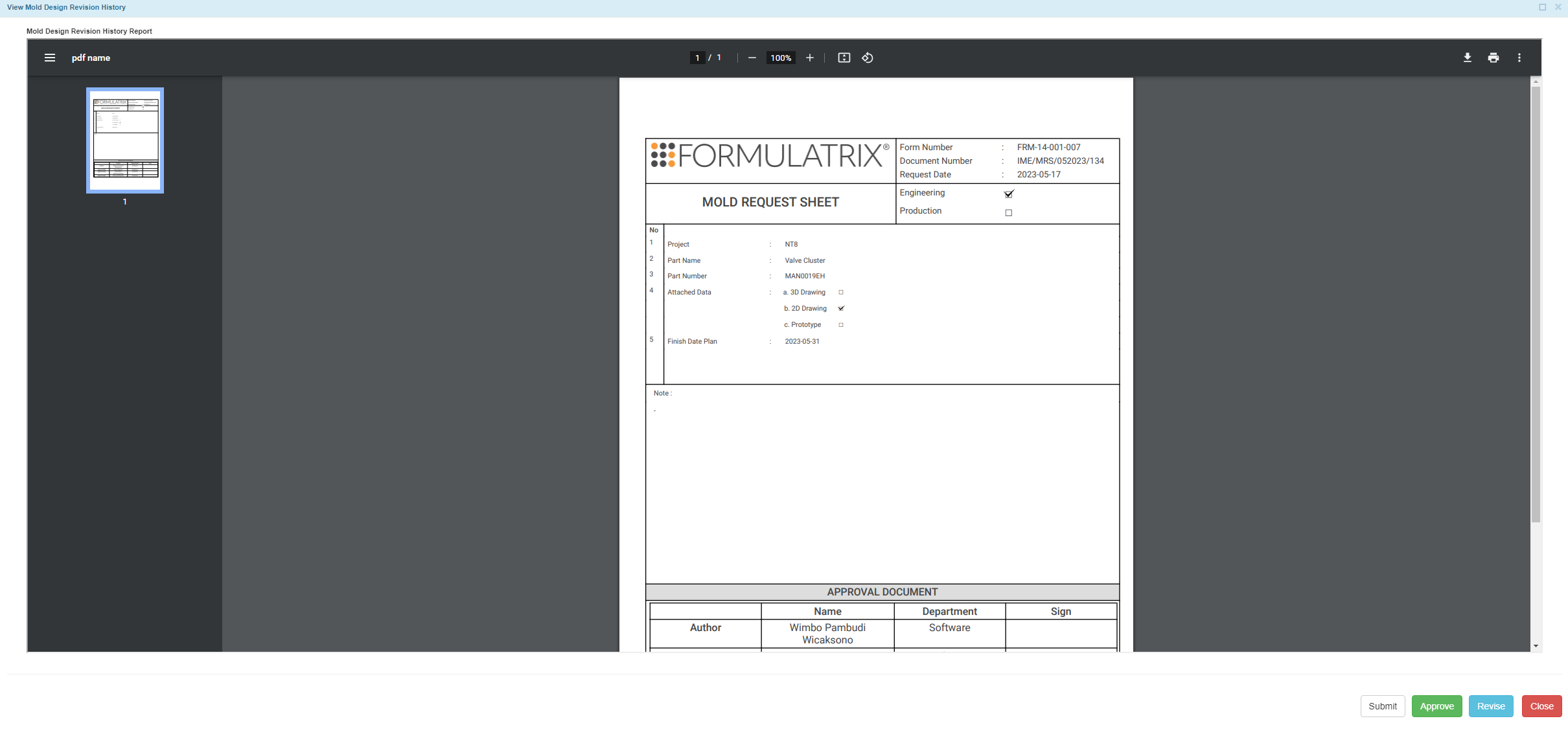
Select View Mold Design Revision History in the Actions button.
Select Submit in the Mold Design Revision History Report window.
Post Condition
TIGA will send a notification email to the verifier and approvers of a mold design request.
Tip
Check the status to track the progress of the Mold Design Revision History record.
Status Name |
Description |
|---|---|
Open |
It is the status of a newly created record. |
Submitted |
This status shows that the record needs approval from approvers. TIGA will send a notification email to the approvers. |
Approved |
All approvers approve the Submitted record. TIGA will later send a notification email to the requester. |
Revised |
The Submitted record is not approved. Tiga will automatically create a Draft record for the requester. Revise the draft before submitting it for approval. |
Approving or Rejecting Mold Design Revision History
Only “Injection” group members can approve or reject the mold design request.
To approve or reject a mold design request:
Access the mold design using one of the following options:
Select View Mold Design Revision History in the Actions button.
From the Mold Design Revision History Report window, select Approve to accept or Revise to reject the record.
Post Condition:
The status of Mold Design Revision History record will turn into Approved, and the system will change the status of the Mold Design record to Design 3D Process after all approvers approve the Mold Design record. If any approver does not approve the request, the system will automatically change the status to Revise and create a new record with a Draft status. Revise and submit the newly created Draft record to submit the Mold Design record.

Approved Mold Design Revision History
Note
TIGA updates the Version field incrementally to show the design history.
Creating or Editing DFMEA and DFMEA Line Items
The design failure mode and effect analysis (DFMEA) mitigates the risk of failure. The mold engineers perform DFMEA to establish and then minimize the part’s Risk Priority Number (RPN). They will ensure that potential hazards are carefully assessed every time the DFMEA evaluation finishes and create a record in the DFMEA table and its line item after the Mold Design Revision History record is Approved. Tiga will change the Mold Design record status to Begin DFMEA when the DFMEA record is created.
Check the description of each field in the DFMEA and DFMEA Line Items window.
DFMEA
Field Name |
Description |
|---|---|
Product# |
Part’s name as written in the Part Name field in the Mold Design window. |
Process# |
Process type. Enter “Injection Molding” for this field. |
Revision# |
Number of revisions made. |
Core Team |
Name of the project the part belongs to. |
Process Responsibility |
Name of the mold engineer involved in the mold design process.. |
Contact (email) |
Process Responsibility personnel’s email address. |
Site |
Molding location. Currently, the molding site is only Formulatrix Salatiga (PSL). |
FMEA Number |
Number of Failure Mode and Effect Analysis (FMEA) meetings. |
Prepared By |
DFMEA record creator’s name. |
FMEA Date (Original) |
Scheduled FMEA meeting date. |
FMEA Date |
FMEA actual meeting date. |
Mold Revision Document Number |
Document number taken from the Mold Design Revision History table. |
DFMEA Line Items
Field Name |
Description |
|---|---|
Potential Failure Mode |
Possible vulnerabilities causing setbacks. |
Potential Effects of Failure |
Possible failure mode effect on customers. |
SEV |
Potential Effects of Failure score. |
Potential Cause(s)/Failure Mechanisms |
Cause of mold failures. |
OCC |
Potential Cause(s)/Failure Mechanisms frequency. |
Detection |
Possible solutions or measures to detect failures. |
DET |
Detection score. |
RPN |
Risk Priority Number calculated from SEV x OCC x DET. |
Recommended Action(s) |
Suggestions to minimize failure and improve the mold design. |
Responsibility and Completion Date |
PIC (mold engineer) of FMEA meeting implementation and expected completion date. |
Action Results |
Result after implementation (progress). |
Action Taken |
Preventive action taken based on potential failures. |
Result SEV |
SEV result after Action Results implementation. |
Result OOC |
OOC result after Action Results implementation. |
Result DET |
DET result after Action Results implementation. |
Result RPN |
RPN result after Action Results implementation. |
Creating or Editing 2D, BoM, and BoM Line Items
Upon approval, the mold engineers will prepare the standardized 2D drawing and Bill of Materials (BoM) of the created mold design record. To do so, create a record in the BoM Mold Design table on the Related Tables. Then, add every component needed in the BoM Line Items. Finally, update the status of the Mold Design table to Closed to indicate mold design process completion.
Mold Design BoM
Field Name |
Description |
|---|---|
Document Number |
Document call number (generated automatically by the system). |
Mold Report Number |
Report Number from Mold Design table. |
Project |
Formulatrix project. |
Mold Name |
Part Name from Mold Design table. |
Release Date |
Mold Design BoM release date. |
Author |
The mold engineer who creates the Mold Design BoM record. |
Revision Number |
Number of revisions made to a record. Tip Write “0” for a new record. |
Mold Design BoM Line Items
Field Name |
Description |
|---|---|
Sub Assy |
Name of a larger manufactured product the requested part belongs to. Complete this field only if the part is a unit assembled separately but designed to be incorporated with other units into a larger manufactured product. |
Part Description |
Part information. |
Part Number (IME) |
Created part call number if manufactured by Formulatrix. |
Part Number (VENDOR) |
Manufacturer or vendor number. Note No need to complete this field if the part has Part Number (IME). |
Category |
Part category (Assembly, OTS, or MTS part). |
Quantity |
Total number of the requested part. |
Material |
Material used for creating the part. |
Raw (mm) |
Part measurement.
|
Weight (kg) |
Estimated weight of the mold design. |
Vendor |
Raw material vendor or suppliers’ name. |
Assembly Part No |
Number given by mold engineers indicating the mold as an assembly part. |
Assembly Description |
Assembling instructions based on Assembly Part No. |
Author |
Record creator’s name. |

