Defining Imaging Settings
Imaging Settings contain imaging instructions about when and how to image an experiment plate. This topic explains how to create a new imaging setting.
Adding a New Imaging Setting
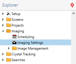
Open the Imaging node on the Explorer and double-click Imaging Settings.

Imaging Settings
Right-click the Imaging Settings table and select Add.

Add Imaging Settings
Click in the new row and type a name for the imaging setting.
At the right of the Imaging Settings table is a list of available imagers. Select whether the imaging setting should be disabled or available for either Visible, Ultraviolet, or SONICC imaging methods by clicking the corresponding option. See Imaging Settings for more information.
OPTIONAL: To adjust settings for various optics and camera controls, select the desired control. Once you select the desired control, you will be able to modify the related setting.
OPTIONAL: Use the table below as a guide to modify the Image Tuning settings.
Title
Options
Leveling mode
Off
No window leveling will be applied.
Manual
The Manual mode lets you set the leveling window manually by defining its lower and upper level limits. The Lower level limit of leveling window defines the boundary below which all tonal values will be discarded from the image. The Upper level limit defines the boundary above which all tonal values will be discarded from the image.
Auto
The Auto mode automatically sets the leveling window according to low and high thresholds. The Low threshold is the percentage of pixels omitted at the left side of the image histogram before setting the lower limit of the tonal range. The High threshold is the percentage of pixels omitted at the right side of the image histogram after setting the upper limit of the tonal range. Auto-leveling has following two modes. Apply per drop applies window leveling to each image according to image’s own histogram. Apply per inspection applies window leveling to each image according to aggregate histogram of images currently being shown. This keeps the relative contrast the same between images currently being shown.
Configuring Optics and Camera Controls
When you add a new imager, you can define several different fields. Some of these fields will show up for certain imagers, some will not.
Optics Control |
Description |
|---|---|
Condenser |
This value indicates the position of the condenser, expressed as the percentage at which the condenser’s iris is closed. The condenser collects light from the Kohler light source and concentrates it onto the well being imaged. Values range from 0 – 100%. At 0%, the iris is fully open, and the cone of light is concentrated at a wide angle. At 100%, the iris is closed, and the light is concentrated in a column, rather than a cone. Hint: Higher condenser values provide greater shadowing around crystals and precipitates in the drop, thereby making them easier to see in the captured image. |
Polarizer |
This value tells you the angle, from 0 to 360 degrees, of the polarizer lens through which the light source is projected. A proper polarizer setting can help generate sufficient contrast in the captured image. |
Dark Field |
This percentage indicates the current brightness of the dark field illumination source that passes through a drop from above. At 0%, the light is turned off, and at 100% the light is at maximum brightness. With dark field illumination, light is scattered throughout the specimen under the microscope so that the specimen appears luminous against a dark background. |
Camera Control |
Description |
|---|---|
Exposure |
The exposure setting can be applied in one of the three following ways:
Exposure Time The exposure time is amount of time, in milliseconds, that the camera’s shutter remains open when capturing an image. This determines the amount of light allowed to fall on the camera’s sensor. Bright Field This value sets the brightness level of the bright-field illumination source that passes through the drop from below. At 0%, the light is turned off, and at 100% the light is at maximum brightness. With bright-field illumination, light is passed through the specimen under the microscope so that the specimen appears dark against a bright background. |
Gamma |
Gamma affects the contrast of the midtones of the image. When you modify this setting, only the midtones are affected, without affecting black and white. |
Resolution |
The resolution is the size of the image in megapixels. To change the resolution, click the drop-down box and select a new resolution. |
Related Topics