Using FRAP Imaging Settings
FRAP Imaging Settings are used with either the FRAP Benchtop ROCK IMAGER or a ROCK IMAGER 1000 with the FRAP imaging method option. There are several tabs and fields on the FRAP imaging setting configuration page. Most of the options related to FRAP appear only after you select FRAP from the Imaging Mode. This topic explains what the various tabs and fields are and how to manipulate them.
FRAP Configurations
Optics Controls
Optics Control |
Description |
|---|---|
Condenser |
The Condenser setting indicates the position of the condenser, expressed as the percentage at which the condenser’s iris is closed. The condenser collects light from the Kohler light source and concentrates it onto the well being imaged. Values range from 0-100%. At 0%, the iris is fully open, and the cone of light is concentrated at a wide angle. At 100%, the iris is closed, and the light is concentrated in a column, rather than a cone. Hint: Higher condenser values provide greater shadowing around crystals and precipitates in the drop, thereby making them easier to see in the captured image. |
Polarizer |
The Polarizer setting indicates the angle, from 0 to 360 degrees, of the polarizer lens through which the light source is projected. A proper polarizer setting can help generate sufficient contrast in the captured image. |
Fluoro Light |
Changing this value affects the fluorescence signal intensity. 100% is the most intense. |
Note
Optics Controls are disabled if you select FRAP imaging mode.
Imaging Modes
Mode |
Description |
|---|---|
Default |
Selecting Default instructs the imager to capture images with visible light. You can then configure basic camera control settings, such as exposure, gain, and resolution. |
Fluorescence (Cy3) |
Selecting this method images drops with fluorescent light. |
FRAP |
FRAP imaging method options include Full Recovery and High Throughput. |
FRAP Mode
The FRAP mode determines what the imager does post-bleaching. You can select one of two available modes (Full Recovery and High Throughput). Use Full Recovery if you are interested in a certain drop. Full Recovery will provide many more images over a shorter period of time, and requires more time. Use High Throughput when inspecting plates for the first time for faster imaging.
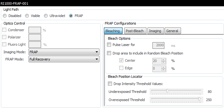
FRAP Configurations
Once you select FRAP as the Imaging Mode and a FRAP Mode (Full Recovery or High Throughput), you can define various other settings. Most of these settings as explained below show up for both FRAP Full Recovery and High Throughput modes.
Bleaching Tab
On the Bleaching tab, you can set options related to the laser, which is what bleaches the drop during FRAP imaging.
Bleach Option |
Description |
|---|---|
Pulse Laser for |
The amount of time in seconds the laser is focused on the drop to bleach the fluorophores. |
Drop area to include in Random Bleach Position |
A bleach position is randomly chosen in the specified area. One or two different bleaching spots can be chosen; near the center of the drop or near the edge of the drop. Concentric rings define the boundary of the area in which a spot is chosen. If 25% area for Edge is specified, then a bleach spot will be performed on the outer 25% area of the drop, whereas the area for the center is defined from the center out. |
Bleach Position Locator |
The Bleach Position Locator is used to help the imager find areas within the LCP drop that are strong candidates for bleaching. Underexposed or overexposed areas within the drop will be ignored based on the values set with the sliders. Zero is black, and 255 is white. With the default settings, the imager will identify all areas within a drop that fall within the 80-255 pixel intensity range and use these areas as bleach spots.
|
Post-Bleach Tab
Select the Full Recovery FRAP post-bleach Options (or HT-FRAP Post-bleach Options if High Throughput FRAP mode selected) to configure options related to what the imager does after the laser bleaches your drop.
Post-Bleach Option |
Description |
|---|---|
Acquire images at fastest rate for (Full Recovery only) |
This setting defines how long, in seconds, the imager will take rapid pictures of your drop after laser bleaching is complete. |
Interval |
The duration of intervals (in seconds) that will be used when taking additional images after the initial imaging process is complete. |
Post-bleach imaging time |
The number of seconds post-bleach imaging will take given the settings you configured on this tab. |
Time to wait before taking end-state images (High Throughput Only) |
The delay time (in seconds) before FRAP captures images of your drops after the bleaching process is complete. |
Imaging Tab
The Imaging tab is where you configure optics and camera settings for your FRAP images.
The imaging tab is divided into 3 areas: Imaging Options, Focusing Options, and Bright Field Focusing.
Section |
Field |
Description |
|---|---|---|
Imaging Options |
Fluorescence Illumination |
The Fluorescence Illumination is the florescent light source. Changing this value affects the fluorescence signal intensity. 100% is the most intense. |
Gamma |
This field affects the contrast of the midtones in the image. |
|
Exposure |
The Exposure field populates with the amount of time in milliseconds that the camera’s shutter remains open when capturing an image, which determines the amount of light allowed to fall on the camera’s sensor, affecting the image’s brightness. |
|
Gain |
The gain setting is used to amplify signal strength in low-light conditions and increase the pixel’s sensitivity to light, in order to make the image brighter. |
|
Focusing Option |
Auto focus Condenser |
The Condenser collects light from the Kohler light source and concentrates it onto the well being examined. Values range from 0 - 100%. At 0%, the iris is fully open, and a cone of light is concentrated at a wide angle. At 100%, the iris is closed, and the light is concentrated in a column of light as opposed to a cone. Adjusting the condenser value can improve image contrast. Increasing the condenser angle increases the contrast. |
Bright Field Focusing |
Bright Field |
This value sets the brightness level of the bright-field illumination source that passes through the drop from below. At 0%, the light is turned off, and at 100% the light is at maximum brightness. With bright-field illumination, light is passed through the specimen under the microscope so that the specimen appears dark against a bright background. |
Gamma |
See “Gamma” in the Imaging Options area. |
|
Exposure |
See “Exposure” in the Imaging Options area. |
|
Gain |
See “Gain” in the Imaging Options area. |
General Tab (Full Recovery only)
The General Settings area provides Curve Fitting Options which apply to the curve FRAP generates based on the pictures taking during the FRAP process.
You can choose one of two component fittings, Single Component Fitting or Double Component Fitting.
Fitting |
Description |
|---|---|
Single Component Fitting |
Selecting this option fits the pixel intensity recovery data with one Bessel function. The result of this numerical fitting is a single diffusion rate. This method is accurate enough for most applications if protein molecules are labeled with dye. |
Double Component Fitting |
Selecting this option fits the pixel intensity recovery data with two Bessel functions. The result of this numerical fit is two distinct diffusion rates. This method is useful if the protein is not purified well. Some small molecule lipids are labeled with dye, which generates the two distinct diffusion rates: diffusion rate of lipids and diffusion rate of protein. |
Related Topics